
Device for controlling air flows

A technology of airflow control device, selection device, applied in the direction of transportation and packaging, air handling equipment, heating/cooling equipment, etc., can solve the problems of reducing the comfort in the car, long time for the valve to reach the desired position, etc., to reduce weight and quantity, shorten the adjustment cycle, reduce the effect of cost

Active Publication Date: 2010-03-24
MAHLE INT GMBH
View PDF1 Cites 6 Cited by
  • Summary
  • Abstract
  • Description
  • Claims
  • Application Information

AI Technical Summary

Problems solved by technology

Especially when unpleasant smells enter the cabin through the outside air, this way of working makes it take too long for the valve to reach the desired position
This will reduce the comfort level in the car

Method used


Image

  • Device for controlling air flows
  • Device for controlling air flows
  • Device for controlling air flows

Examples


Embodiment Construction

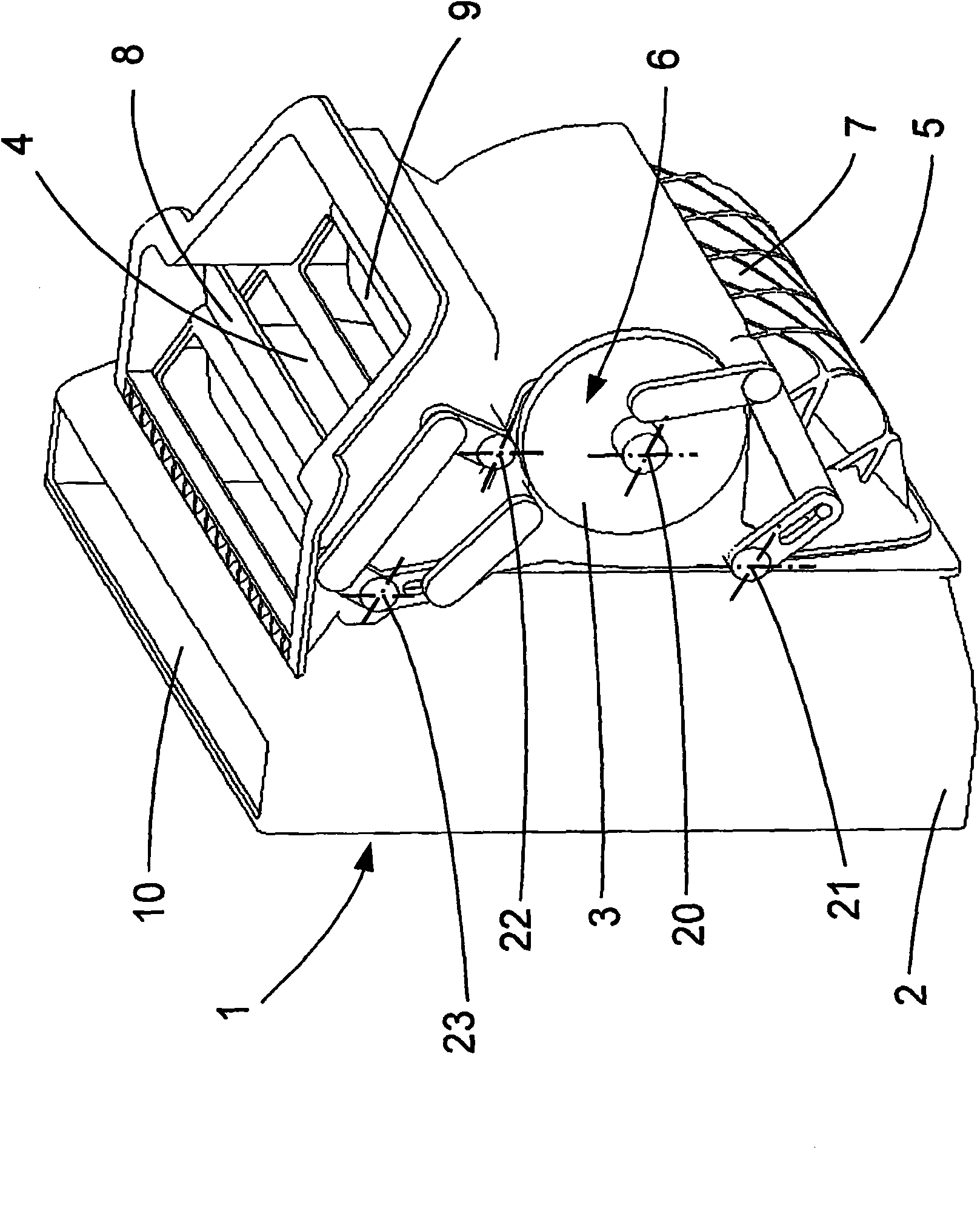
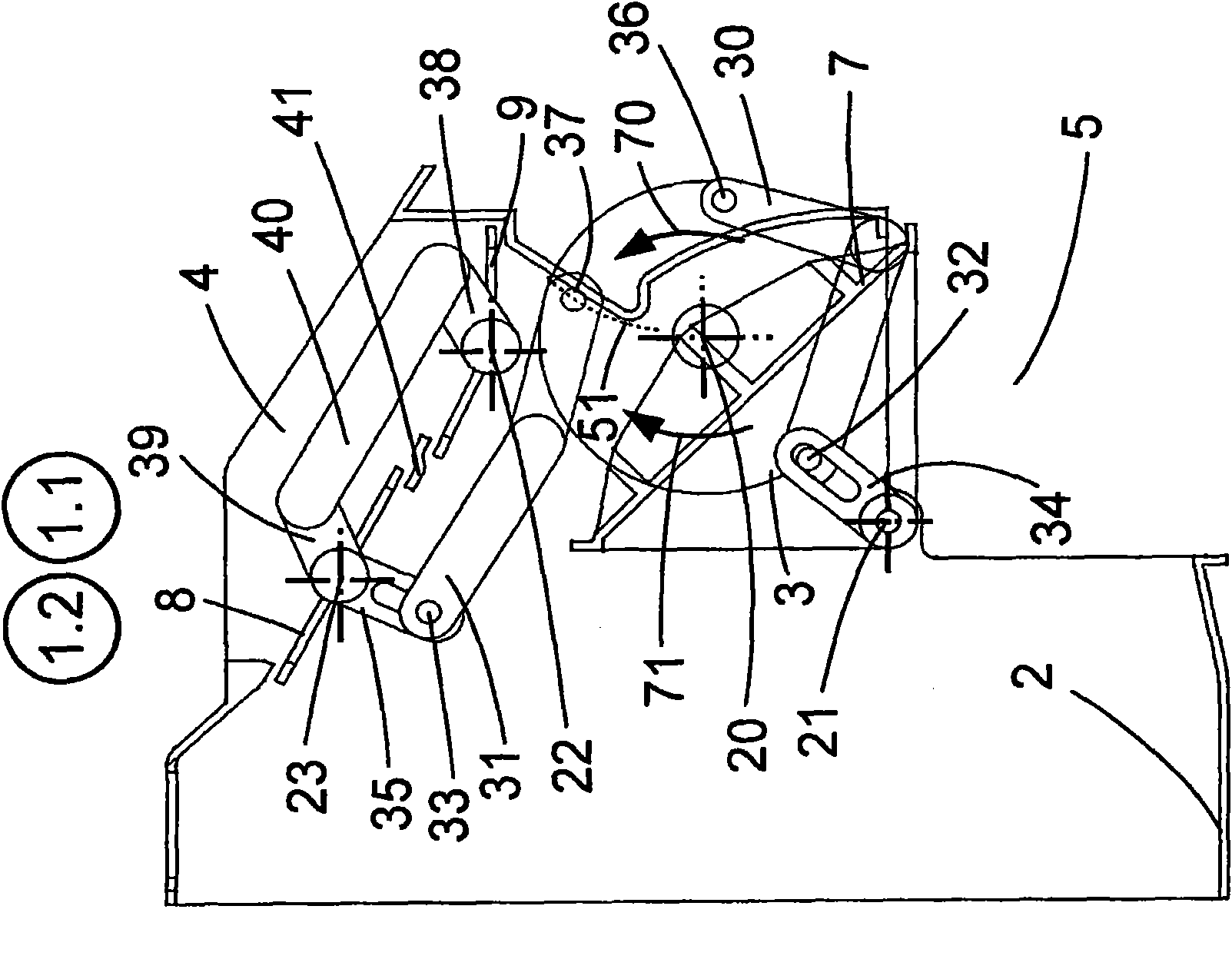
[0033] Figure 1 is a perspective view of a device in one embodiment of the invention. The housing 2 has an inflow channel 4 with an inflow section for the inflow of external air and an inlet 5 through which the airflow enters, in particular in recirculated air mode, from the vehicle compartment. In addition, the housing 2 also has an opening 10 for installing or removing a filter (not shown). In the region of the inflow channel 4 for the external air flow, two external air valves 8 , 9 are arranged, which are each arranged in the housing 2 via a fixed rotational axis 23 , 22 . The external air valves 8 and 9 are respectively a throttling valve. A recirculation air valve 7 is arranged in the region of the recirculation air inlet 5 , which is likewise arranged in the housing 2 via a fixed rotational axis 21 . The circulating air valve 7 is formed by a cylindrical segment cut out.

[0034] Arranged between the valves 7 , 8 , 9 is a power module 6 , which is arranged in the hou...


PUM


Abstract

The invention relates to a device for controlling air flows, particularly for air conditioners of motor vehicles, comprising a flap arrangement having at least two flaps, wherein the flaps of the flap arrangement can pivot between a first and a second position; a drive; a kinematic module that is coupled to the flap arrangement and can be moved in a first movement direction by the drive, thereby pivoting the flaps from the first into a second position, and that can be moved in a second movement direction by the drive, thereby pivoting the flaps from the second into the first position, whereinthe device comprises the following: input means for inputting a desired position of the flaps; detection means for detecting an actual position of the flaps; selection means for selecting either the first or second movement direction, by which the flaps can be pivoted faster from the actual position to the desired position; and control means for actuating the drive such that the kinematic module pivots the flaps in the movement direction selected by the selection means from the actual to the desired position.

Description

technical field [0001] The invention relates to a device for distributing and / or controlling an air flow, in particular in a vehicle air conditioning system. Background technique [0002] Depending on the temperature to be achieved in the vehicle compartment, the air conditioner requires conditioning of the external air taken in during operation, which is usually performed by heat exchangers and evaporators. Conditioned air is sent to the cabin. Here, the air-conditioning system can be operated in the following modes: fresh air mode (air is sucked in from the outside and then conditioned and fed into the cabin) or recirculated air mode (air is drawn in from the cabin instead of outside) Adjust handling before returning to the compartment). But there are also adjustable modes in which a part of fresh air is mixed with a part of recirculated air. This mixing is usually achieved in a device arranged under the windshield by adjusting valves, which open or close to change the ...

Claims


Application Information

Patent Timeline
Patent Type & Authority Applications(China)
IPC IPC(8): B60H1/00
CPCB60H1/00842B60H1/00835
Inventor 赖因霍尔德·罗斯萨沙·林道尔诺贝特·奥特泽尔贝格尔哈拉尔德·米莱森
Owner MAHLE INT GMBH
Learn More