Multi-insurance self-control anti-theft lock

A technology of locks and electronically controlled locks, applied in the field of multi-insurance self-control anti-theft locks, can solve problems such as insurmountable defects of mechanical lock cylinders, and achieve the effects of increasing anti-theft performance, mature and reliable technology, and safe and reasonable design.

Inactive Publication Date: 2012-03-28
郑小军
View PDF6 Cites 11 Cited by
  • Summary
  • Abstract
  • Description
  • Claims
  • Application Information

AI Technical Summary

Problems solved by technology

[0003] The technical problem to be solved by the present invention is that the inherent defects of the mechanical lock cylinder cannot be overcome. It is trying to find a safe, simple in structure, low cost and multi-insurance self-control anti-theft lock outside the mechanical lock cylinder.

Method used


Image

  • Multi-insurance self-control anti-theft lock
  • Multi-insurance self-control anti-theft lock
  • Multi-insurance self-control anti-theft lock

Examples


Embodiment 1

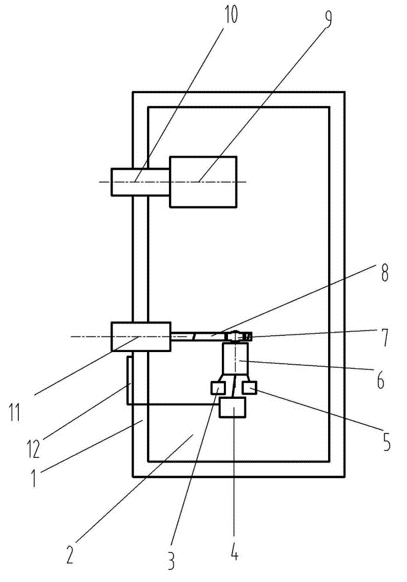
[0022] Such as figure 1 As shown, the multi-insurance self-control anti-theft lock provided by the present invention includes a lock chamber 2 and a mechanical lock cylinder 9 and a mechanical bolt 10 fixed on the lock chamber 2, and the anti-theft lock also includes a set of fixed Electric control lock core in lockset cavity 2; This electric control lock core comprises a micro stepping motor 6, a gear 7 installed on the 6 shafts of this micro stepping motor, a rack 8 meshed with gear 7, a An electric deadbolt 11 connected to the end of the rack 8, a single-chip microcomputer 4 for controlling the micro-stepping motor 6, and a DC main power supply 3 for the micro-stepping motor 6 and the single-chip microcomputer 6 to supply power. The electric deadbolt 11 is matched with an independent lock hole on the door frame. The electric lock cylinder control also includes a wireless signal controller, and the signal of the wireless signal controller is sent by a remote control key, or...

Embodiment 2

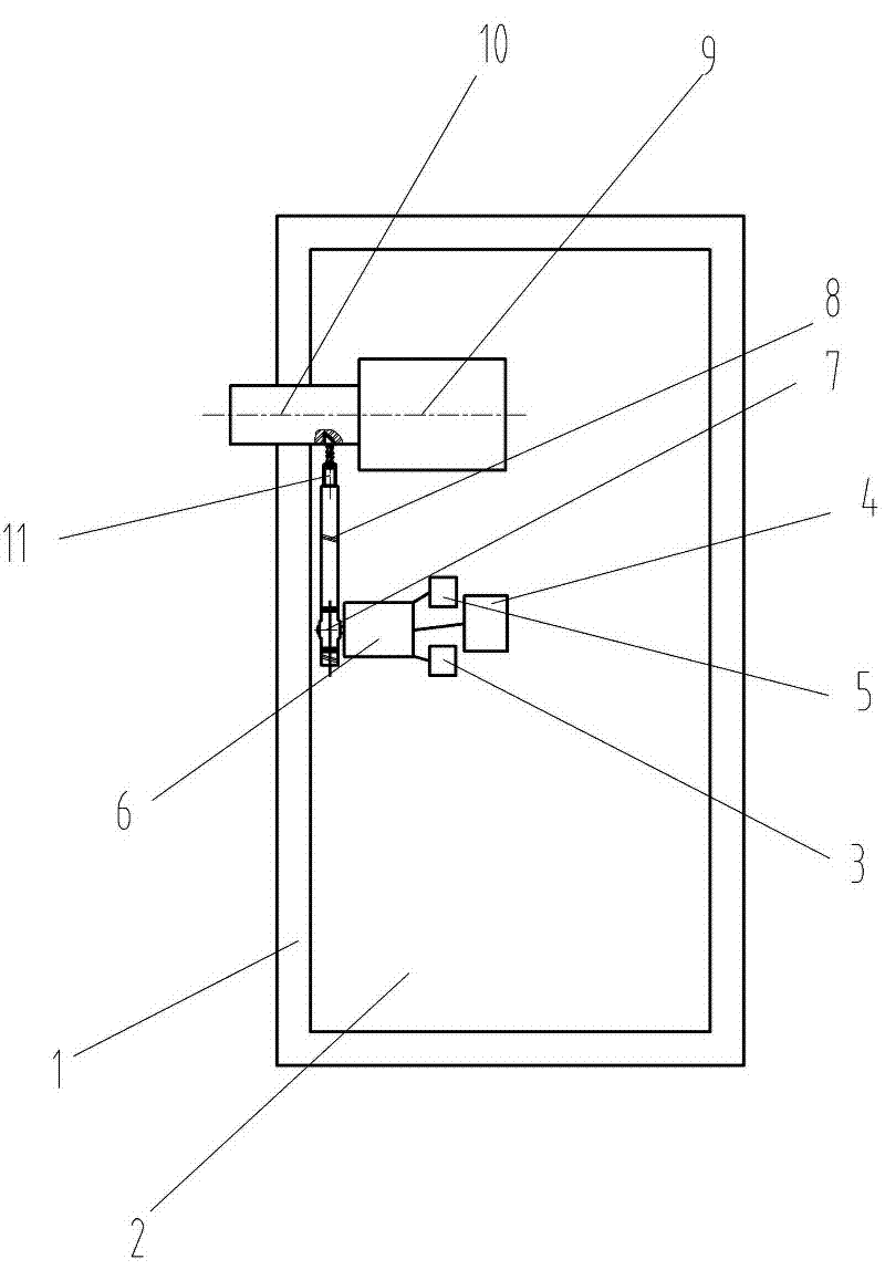
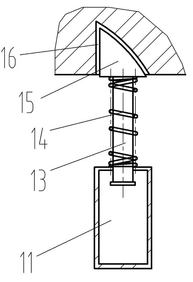
[0024] Such as figure 2 with image 3 As shown, the multi-insurance self-control anti-theft lock provided by the present invention includes a lock chamber 2 and a mechanical lock cylinder 9 and a mechanical bolt 10 fixed on the lock chamber 2, and the anti-theft lock also includes a set of fixed Electric control lock core in lockset cavity 2; This electric control lock core comprises a micro stepping motor 6, a gear 7 installed on the 6 shafts of this micro stepping motor, a rack 8 meshed with gear 7, a An electric deadbolt 11 connected to the end of the rack 8, a single-chip microcomputer 4 for controlling the micro-stepping motor 6, and a DC main power supply 3 for the micro-stepping motor 6 and the single-chip microcomputer 6 to supply power. The electric lock tongue 11 cooperates with the wedge-shaped groove 16 at the bottom of the mechanical lock tongue 10 . The end of the electric deadbolt 11 is a wedge-shaped block 15, and a connecting rod 13 is fixed at the bottom o...


PUM


Abstract

The invention discloses a multi-insurance self-control anti-theft lock, wherein the anti-theft lock comprises a lock cavity and a mechanical lock cylinder and a mechanical spring bolt which are fixed on the lock cavity; the anti-theft lock further comprises a set of electronic control lock cylinder which is fixed in the lock cavity; the electronic control lock cylinder comprises a micro stepping motor, a gear mounted on the shaft of the micro stepping motor, a rack engaged with the gear, an electronic control lock cylinder connected with the end part of the rack, a single-chip for controlling the micro stepping motor, and a main direct-current power source for supplying power to the micro stepping motor and the single-chip. The technical solution in the invention adds a set of micro electronic control lock cylinder in the original cavity of a mechanical lock; the electronic control lock cylinder comprises a micro stepping motor, a micro gear, a micro rack, a single-chip control chip and a power source; and the structure applies prior mature electrical parts and mechanical parts; so the multi-insurance self-control anti-theft lock is small in realizing difficulty, low in cost and easy to be promoted and applied in large areas.

Description

technical field [0001] The invention relates to an anti-theft lock set for an anti-theft door, in particular to a multi-insurance self-control anti-theft lock set for an anti-theft door. Background technique [0002] At present, anti-theft locks are installed on the anti-theft doors used in households. The anti-theft locks are mainly mechanical locks, that is, a rotating mechanism driven by a lock cylinder and a lock cylinder. The rotating mechanism drives the dead bolt to move between the door frame and the door leaf. The anti-theft function is achieved by matching the teeth of the key with the spring copper column in the lock cylinder, but the current thief can use an iron wire to open the anti-theft door lock, thus losing the meaning of anti-theft. For this reason, the anti-theft lock design The latter has worked hard to improve the complexity of the mechanical lock cylinder, but after all, it is a mechanical lock cylinder and needs to be inserted with a key, which still...

Claims


Application Information

Patent Timeline
Patent Type & Authority Applications(China)
IPC IPC(8): E05B63/14E05B47/02E05B49/00E05B15/10E05B15/12
Inventor 郑小军
Owner 郑小军
Why Eureka
Try Eureka