Water-gas dual-purpose filling valve

A technology for filling valves and air valves, applied in the field of water-air dual-purpose filling valves, which can solve the problems of expensive filling valves, occupying storage space, unfavorable production costs, etc.

Active Publication Date: 2014-06-18
GUANGZHOU TECH LONG PACKAGING MACHINERY CO LTD
View PDF9 Cites 0 Cited by
  • Summary
  • Abstract
  • Description
  • Claims
  • Application Information

AI Technical Summary

Problems solved by technology

[0003] Although the above-mentioned existing filling valve can realize the basic functions of its filling operation, it has many deficiencies in its own structure and performance in actual use, and cannot achieve the best use effect.
Its shortcoming is that filling valves with different composition principles are only suitable for filling the same type of materials. Specifically, in general, filling non-gas liquids, such as purified water, fruit juice, milk, etc., generally use normal pressure Filling methods, and gas-containing materials such as soda, wine, etc. generally use positive pressure filling valves, negative pressure filling valves or pressurized filling valves
However, it is often necessary to exchange filling gas-containing materials and non-gas materials on the same filling production line, so that a filling valve has to be equipped for gas-containing materials and another filling valve for non-gas materials However, there are as many as 100 sets of filling valves used for filling one material in a canning machine. In addition to the high price of the filling valve itself, it has to be disassembled and assembled when used, which takes up manpower and takes up production time. It also takes up storage space, which is not conducive to saving production costs

Method used


Image

  • Water-gas dual-purpose filling valve
  • Water-gas dual-purpose filling valve
  • Water-gas dual-purpose filling valve

Examples


Embodiment Construction

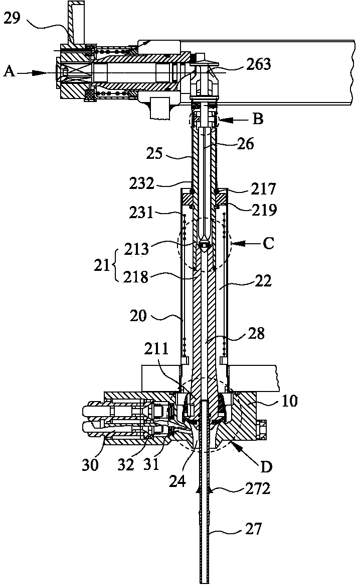
[0048] First, please refer to Figure 1 to Figure 5 As shown, it shows the specific structure of the preferred embodiment of the present invention, including the valve seat 10 and the valve body 20 fixed on the valve seat 10 .

[0049]The valve seat 10 is provided with a filling cylinder 11, the valve body 20 is a cylindrical hollow tube, and a liquid valve spool 21 that can move up and down is vertically arranged in the valve body 20, and the liquid valve spool 21 includes a valve stem 218 And valve stem sleeve 213, valve stem 218 lower end is provided with liquid valve valve head 211, and the valve seat 10 of liquid valve valve head 211 periphery has filling mouth 24, and liquid valve valve head 211 seals tightly in filling mouth 24, The upper end of the valve stem sleeve 213 extends out of the top end of the valve body 20 . A liquid inlet channel 22 is formed between the liquid valve spool 21 and the inner wall of the valve body 20, and the liquid inlet channel 22 communic...


PUM


Abstract

The invention discloses a water-gas dual-purpose filling valve, which comprises a valve seat and a valve body fixedly arranged on the valve seat, wherein a hydraulic valve core which can move up and down is arranged in the valve body; a liquid inlet channel is formed between the hydraulic valve core and the valve body; a gas channel is arranged in the hydraulic valve core; a gas valve core which can up and down is arranged in the gas channel; the top end of the hydraulic valve core is fixedly provided with a clamping block; the top end of the gas valve core is provided with a pushing step; when the filling valve is used for filling, a certain distance is reserved between the clamping block and the pushing step; when the filling valve is used for filling gas-containing materials, the distance that the gas valve core moves upwards is not more than the distance between the clamping block and the pushing step; and when the filling valve is used for filling water, the distance that the gas valve core moves upwards is more than the distance between the clamping block and the pushing step, the clamping block is jacked to drive the hydraulic valve core to be lift to an appropriate openness at the same time of lifting the jacking step upwards, therefore filling of gas-containing materials and gas-free materials is realized on the same filling valve, and troubles because the traditional gas-containing materials and the gas-free materials are finished by different filling valves are avoided.

Description

technical field [0001] The invention relates to the field of filling equipment, in particular to a water-gas dual-purpose filling valve capable of filling gas-containing and gas-free materials. Background technique [0002] Filling is a technology used to fill various materials such as gas-containing liquids and non-gas liquids into various packaging containers such as bottles, cans, boxes, barrels or bags. The use of mechanized filling can not only improve productivity, Reduce product loss, ensure packaging quality, and reduce mutual pollution between the production environment and the loaded materials. Therefore, the current filling technology has been widely used in the automatic filling production of pharmaceutical, daily chemical, food and special industry factories. To complete the filling, the filling valve is an essential and important part. According to the filling principle, the filling valve can be divided into normal pressure filling valve, positive pressure fil...

Claims


Application Information

Patent Timeline
Patent Type & Authority Patents(China)
IPC IPC(8): B67C3/26B67C3/28
Inventor 吴茂柿谢棋柏
Owner GUANGZHOU TECH LONG PACKAGING MACHINERY CO LTD
Why Eureka
Try Eureka