Radiating device for laser

A technology for heat sinks and lasers, applied in lasers, laser parts, phonon exciters, etc., can solve the problems affecting the quality and power of laser beams, the development of laser miniaturization, the speed of convection is not fast enough, the convection area is not large enough, etc. The problem is to achieve the effect of obvious heat conduction effect, obvious convection effect and good convection effect.

Inactive Publication Date: 2012-03-21
SUZHOU DAHENG OPTICS & FINE MECHANICS
View PDF10 Cites 0 Cited by
  • Summary
  • Abstract
  • Description
  • Claims
  • Application Information

AI Technical Summary

Problems solved by technology

[0004] Most of the current cooling devices for lasers are to install a heat sink at the end of the laser, and then install a fan at the back. The airflow output by the fan blows to the heat sink and flows out. The convection area is not large enough, and the convection speed is not fast enough.
Therefore, the heat dissipation effect is not good, which affects the improvement of the beam quality and power of the laser and the development of laser miniaturization.

Method used


Image

  • Radiating device for laser
  • Radiating device for laser
  • Radiating device for laser

Examples


Embodiment Construction

[0027] The technical implementation process of the present invention will be further described below in conjunction with the accompanying drawings and embodiments.

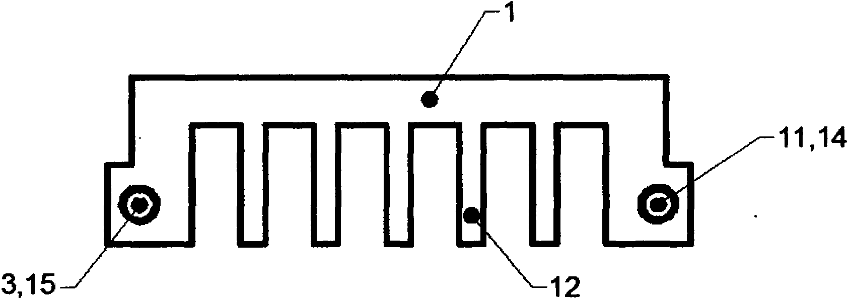
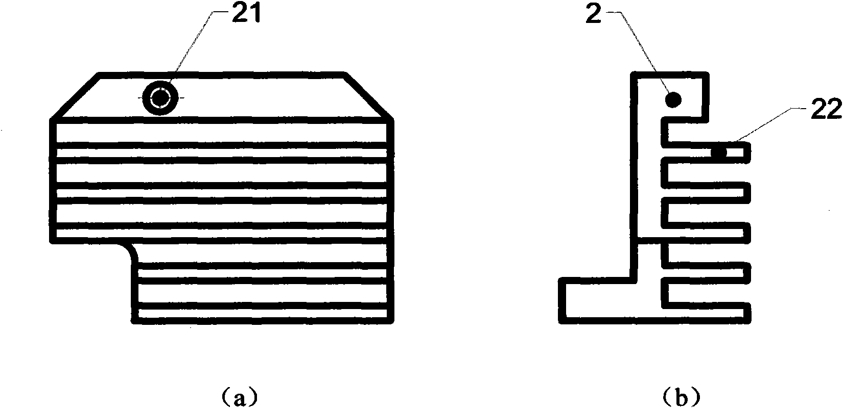
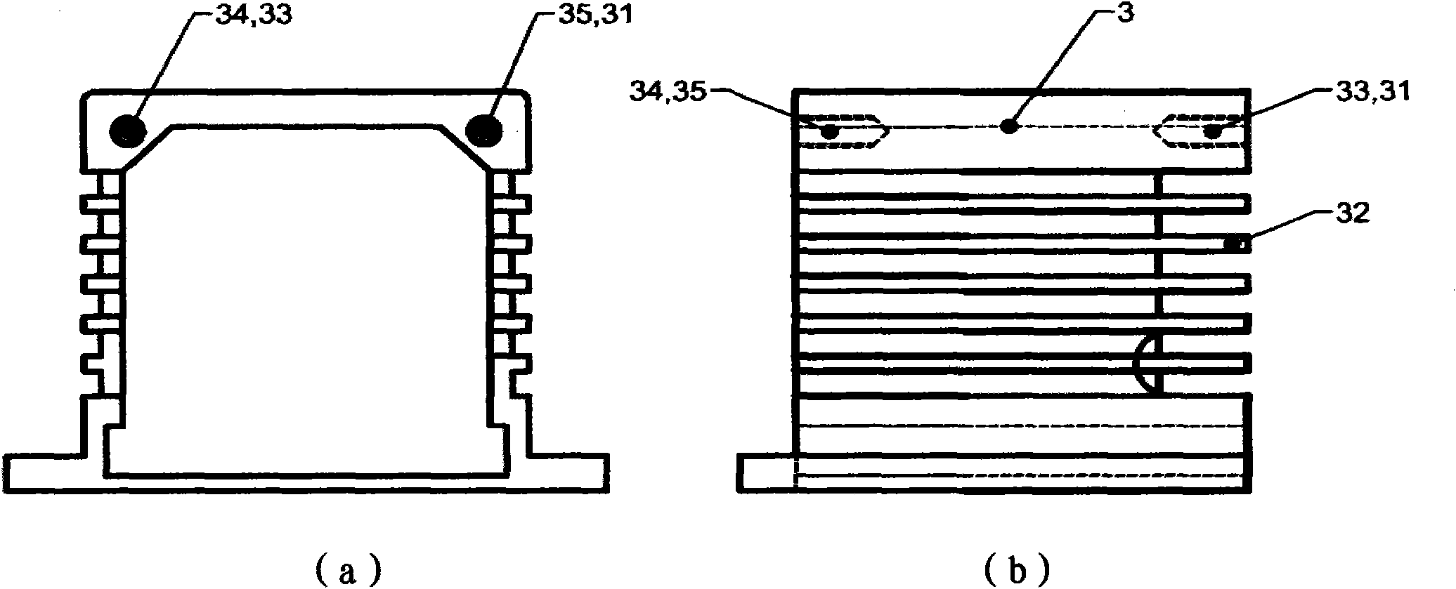
[0028] see Figure 1 to Figure 5 As shown, a heat dissipation device for a laser includes a fan, and also includes a heat sink 2, the heat sink 2 is installed at the tail of a base plate 1, the base plate 1 is inserted into an outer shell 3, and is installed in front of the outer shell 3 A front end cover 4, the fan 5 is installed behind the outer casing 3.

[0029] Further, the bottom plate 1 includes a first groove structure 12 .

[0030] Further, the heat sink 2 includes a second groove structure 22 .

[0031] Further, the front cover 4 also has a laser transmission hole 41 .

[0032] Further, the front cover 4 includes a second comb structure 42 .

[0033] Further, the outer casing 3 includes a first comb structure 32 .

[0034] Further, in order to enable the heat sink 2 to be well ventilated, the second...


PUM


Abstract

The invention discloses a radiating device for a laser. The radiating device comprises a fan and a radiating fin, wherein the radiating fin is arranged on the rear part of a base plate; the base plate is inserted into an outer shell body; a front end cover is arranged on the front surface of the outer shell body; the fan is arranged on the back surface of the outer shell body; the base plate comprises a first concave groove structure; the radiating fin comprises a second concave groove structure; the front end cover comprises a second comb-shaped structure; and the outer shell body comprises a first comb-shaped structure. The radiating device for the laser has the characteristics of large convection area, high speed, good convection effect, large heat-conductive area, obvious radiation, simple and compact structure, low manufacturing cost and easy popularization and use.

Description

technical field [0001] The invention relates to a heat dissipation device, in particular to a heat dissipation device for a laser. Background technique [0002] During the working process of the all-solid-state laser, the pump light is focused in the laser crystal to provide energy for the laser oscillation, but factors such as quantum defects and non-radiative transitions in the crystal cause a large amount of heat to be generated, that is, part of the energy of the pump light Instead of being converted to laser output, it becomes waste heat in the crystal, resulting in thermal effects of the crystal. [0003] The thermal effects of laser crystals mainly include thermally induced birefringence, thermal depolarization and thermal lensing. The temperature tolerance range of nonlinear crystal phase matching is limited, and the temperature requirement is high, so the heat generated in the laser seriously affects the output power, polarization state and beam quality of the lase...

Claims


Application Information

Patent Timeline
Patent Type & Authority Applications(China)
IPC IPC(8): H01S3/042
Inventor 王勇王宪涛王斌王利吴爱平吴文兵唐小赓朱红超罗华前
Owner SUZHOU DAHENG OPTICS & FINE MECHANICS
Why Eureka
Try Eureka