Phase diaphragm capable of measuring optical nonlinearity of material

A technology of optical nonlinearity and phase aperture, which is applied in the measurement of phase influence characteristics, polarization elements, etc., and can solve problems such as sensitivity influence

Inactive Publication Date: 2012-03-21
SUZHOU MICRONANO LASER PHOTON TECH CO LTD
View PDF1 Cites 9 Cited by
  • Summary
  • Abstract
  • Description
  • Claims
  • Application Information

AI Technical Summary

Problems solved by technology

The sensitivity of the measurement is affected to a cert...

Method used


Image

  • Phase diaphragm capable of measuring optical nonlinearity of material
  • Phase diaphragm capable of measuring optical nonlinearity of material
  • Phase diaphragm capable of measuring optical nonlinearity of material

Examples


Embodiment Construction

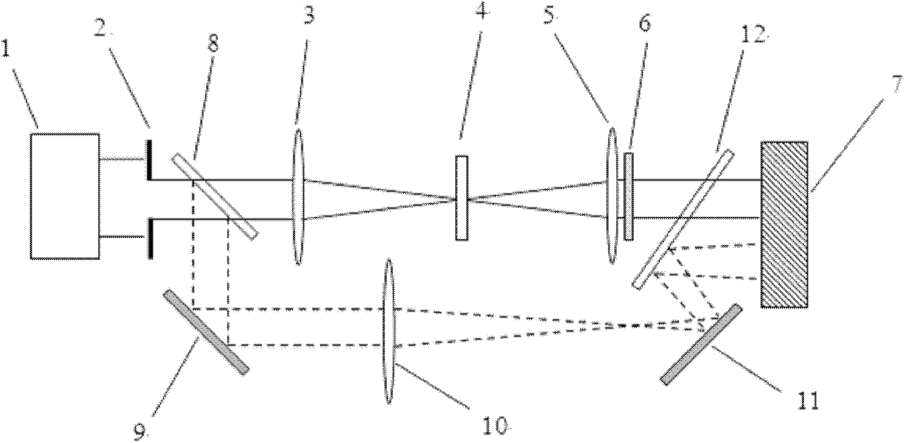
[0045] The experimental setup of the 4f phase coherent imaging system is as follows: figure 1As shown, the experimental setup can be divided into two parts, the measurement system and the energy reference system. The measurement system consists of a laser 1 , a phase diaphragm 2 , a convex lens 3 , a sample to be measured 4 , a convex lens 5 , a neutral filter 6 and a CCD camera 7 . The convex lens 3 and the convex lens 5 constitute a 4f system, the phase diaphragm 2 is placed on the object plane of the 4f system, the sample 4 to be tested is on the Fourier plane, and the CCD camera 7 receives the pulse image on the image plane of the 4f system. The laser light emitted from the laser first undergoes beam expansion (this part is in figure 1 omitted in ), the expanded laser pulse passes through the phase diaphragm to form near top-hat light, and the light beam converges to the sample to be measured placed on the Fourier surface through the Fourier transform of the convex lens 3...


PUM


Abstract

The invention discloses a phase diaphragm (2) capable of measuring optical nonlinearity of material, comprising a phase object (13), wherein the phase delay between the phase object (13) and the phase diaphragm (2) is Pi/2; the phase object (13) is a symmetrical square. The invention can effectively measure and distinguish the size and symbol of the third-order nonlinear refraction coefficient of a medium without influencing the measuring sensitivity.

Description

technical field [0001] The invention relates to a phase aperture capable of measuring material optical nonlinearity. Background technique [0002] With the rapid development of technologies in the fields of optical communication and optical information processing, research on nonlinear photonic materials is becoming increasingly important. The realization of functions such as optical logic, optical storage, optical transistor, and optical switch mainly depends on the research progress of nonlinear photonics materials. The measurement technology of optical nonlinear parameters of medium is the key technology to study nonlinear optical materials. The 4f phase coherent imaging system (G.Boudebs and S.Cherukulappurath, "Nonlinear optical measurements using a 4f coherent imaging system with phas eobject", Phys.Rev.A, 69, 053813 (1996)) is a measurement proposed in recent years New approaches to nonlinear refraction and absorption in materials. [0003] The 4f phase coherent im...

Claims


Application Information

Patent Timeline
IPC IPC(8): G02B5/30G01N21/41
Inventor 宋瑛林聂仲泉刘南春石光杨俊义
Owner SUZHOU MICRONANO LASER PHOTON TECH CO LTD
Why Eureka
Try Eureka