
Control device for gas-extracting pipeline

A control device and gas extraction technology, applied in valve device, gas discharge, safety device, etc., can solve the problems of short service life, high energy consumption, low efficiency of the extraction system, etc. Reasonable structure and improved efficiency

Inactive Publication Date: 2012-03-21
王景熙
View PDF6 Cites 2 Cited by
  • Summary
  • Abstract
  • Description
  • Claims
  • Application Information

AI Technical Summary

Problems solved by technology

It can be seen that the existing underground gas drainage methods have the following shortcomings: the use of the drainage system is not reasonable enough, the drainage capacity is not well utilized, and the efficiency of the entire drainage system is low; the drainage device in the drainage system Short service life and high energy consumption

Method used


Image

  • Control device for gas-extracting pipeline
  • Control device for gas-extracting pipeline
  • Control device for gas-extracting pipeline

Examples


Embodiment Construction

[0009] The present invention is further described below in conjunction with embodiment and accompanying drawing.

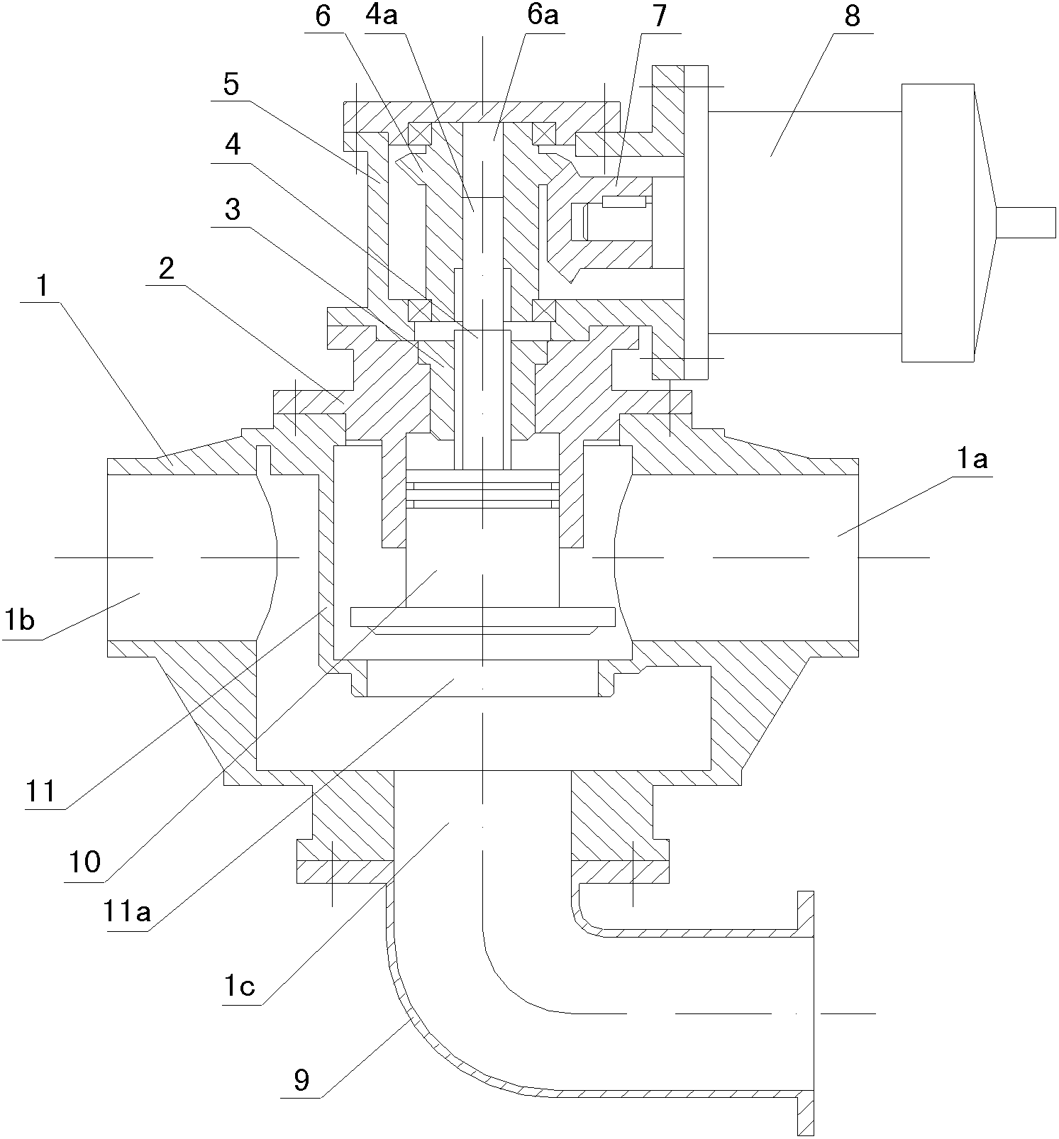
[0010] see figure 1

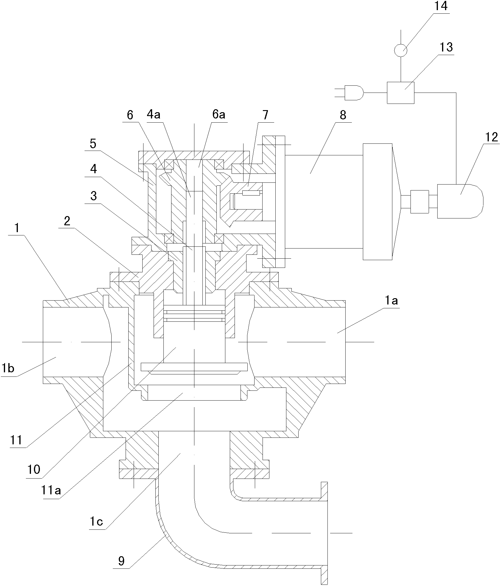
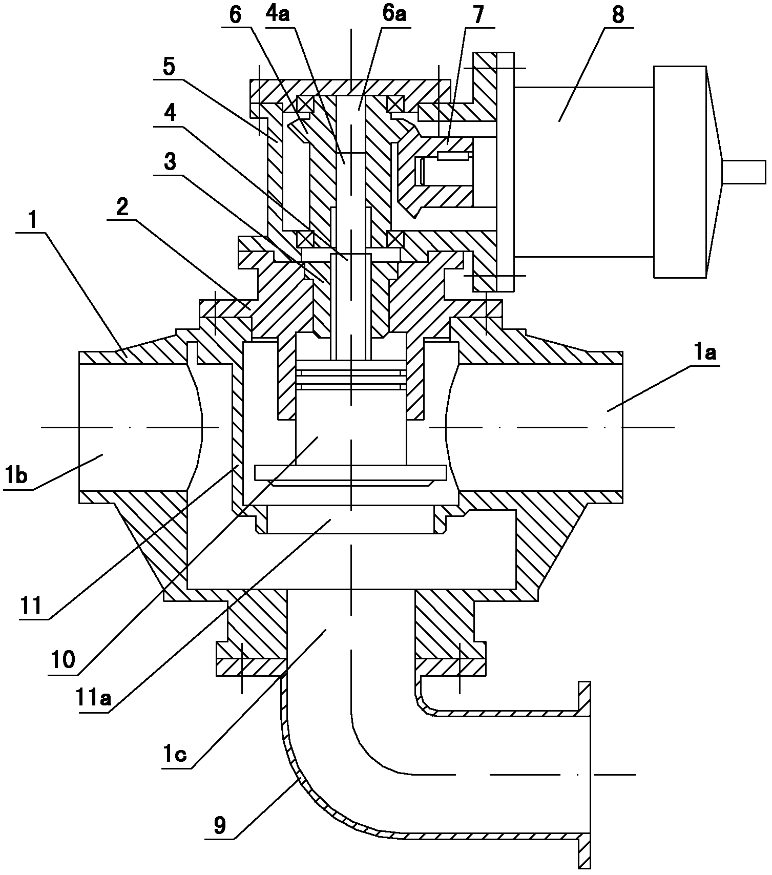
[0011] The gas drainage pipeline control device provided by the present invention has a valve body 1, the inner cavity of the valve body 1 has a valve seat 11 with both ends open, and the through hole 1b opened at one end of the valve body 1 communicates with its inner cavity, The through hole 1a opened at the other end communicates with the valve seat 11. The valve body 1 is connected with a seat body 2. A nut 3 is fixed inside the seat body 2. A threaded screw 4 passes through the seat body 2 and cooperates with the nut 3. The threaded screw 4 The lower end extends into the valve seat 11 and is connected with a valve core 10, and the valve core 10 is aligned with the opening 11a at the lower end of the valve seat 11.

[0012] The control mechanism includes a driving bevel gear 7, a driven bevel gear 6, and a reducer 8. The driven bevel ge...


PUM


Abstract

The invention relates to a control device for a gas-extracting pipeline. A valve base with two opened ends is arranged in an inner cavity of a valve body; a through hole formed at one end of the valve body is communicated with the inner cavity of the valve body; the through hole formed at the other end of the valve body is communicated with the valve base; a base body is linked with the valve base; a nut is fixed in the base body; a screw rod passes through the base body and is matched with the nut; the lower end of the screw rod is inserted into the valve body and is connected to a valve core; the valve core is aligned with an opening at the lower end of the valve base; and the upper part of the screw rod is in transmission match with a control mechanism. The control device for the gas-extracting pipeline is mounted on a branch pipe for extracting the gas; when the gas density in one branch pipe is lower, the control mechanism controls the valve core to close the opening at the lower end of the valve base so as to separate the branch pipe; and when the gas density in the branch pipe is higher, the control mechanism controls the valve core to lift so as to conduct the branch pipe. The control device provided by the invention can be used for promoting the efficiency of a pumping system and greatly prolonging the service life of a pumping device.

Description

technical field [0001] The invention relates to a pipeline on-off control device, in particular to a control device installed on an underground gas drainage pipeline for controlling its on-off. Background technique [0002] At present, the method of extracting the gas under the mine is to collect the gas from each gas escape source into a main pipe through the extraction branch pipeline, and then use the drainage system to drain the gas in the main pipeline. Since the gas emission from each gas emission source is not a constant, when the gas concentration in some branch pipelines is low, when they are still connected to the main pipeline, the extraction system will cause exhaustion. The waste of power consumption of the drainage system, when the gas concentration in some extraction branch pipelines is low, if these branch pipelines are closed, the power consumption of the drainage system can be reduced and the drainage efficiency can be improved. It can be seen that the dis...

Claims


Application Information

Patent Timeline
Patent Type & Authority Applications(China)
IPC IPC(8): F16K31/04E21F16/00E21F7/00
Inventor 王景熙
Owner 王景熙
Learn More