
Communication network energy efficiency optimization control system

A communication network and optimization control technology, applied in the field of communication, can solve the problem that the energy consumption optimization effect of the whole network needs to be improved, and achieve the effect of energy efficiency optimization

Pending Publication Date: 2022-04-12
国网山东省电力公司冠县供电公司
View PDF10 Cites 0 Cited by
  • Summary
  • Abstract
  • Description
  • Claims
  • Application Information

AI Technical Summary

Problems solved by technology

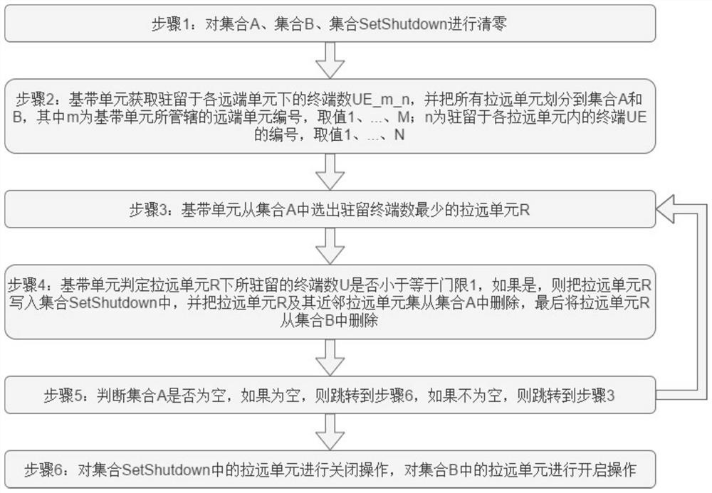
[0006] In the existing network, remote units are responsible for terminal coverage, and their number is closely related to traffic demand and coverage area. Today, with the rapid increase in traffic and the ubiquitous development of mobile communications, the number of remote units will increase exponentially. The energy consumption of the access network will account for the vast majority of the energy consumption of the access network. However, as analyzed above, the focus of the existing technology on the energy consumption control of the access network starts with product design (corresponding to the first solution), on the one hand, On the other hand, it starts from the energy consumption control of the equipment in the computer room in the product application (such as core side equipment, base station baseband pool equipment, corresponding to the second solution), but fails to control energy consumption from the remote equipment that occupies a considerable share , which leads to the need to improve the energy consumption optimization effect of the entire network. Therefore, it is a problem to be solved in the industry to propose a method based on the energy consumption control of the remote unit to optimize the energy consumption of the access network.

Method used


Image

  • Communication network energy efficiency optimization control system
  • Communication network energy efficiency optimization control system
  • Communication network energy efficiency optimization control system

Examples


Embodiment

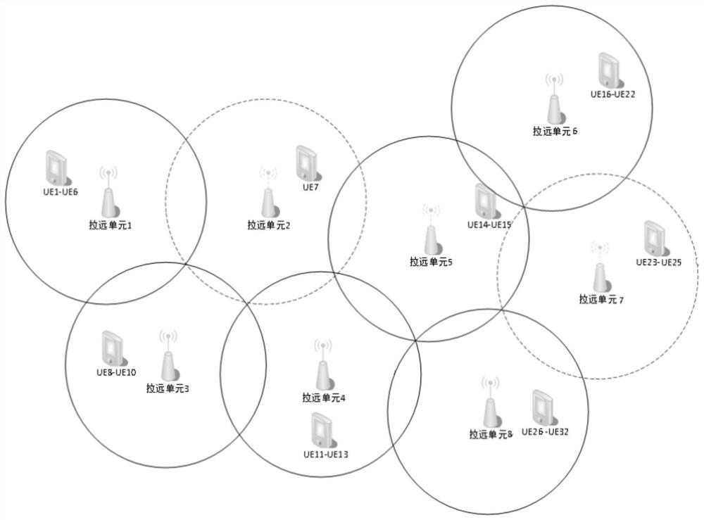
[0072] Example: such as image 3 As shown, the remote unit subsystem in this embodiment includes 8 remote units, namely remote unit 1, remote unit 2, remote unit 3, remote unit 4, remote unit 5, remote unit 6, The remote unit 7 and the remote unit 8 have 32 UEs accessing the network, that is, UE1-UE32. In this embodiment, the fingerprint method is used for positioning, and the position of the terminal is calculated based on the received power (measurement amount) of the uplink signal. In this embodiment, The time cycle trigger scheme is adopted, that is, according to the preset cycle (2 seconds in this embodiment), the start-stop judgment and start-stop operation of the remote unit is triggered once per cycle. In addition, the present embodiment determines that the neighbors of the remote unit R are far away The unit set method is as follows: the coordinates of the remote unit R are the center, and the remote units within the radius T are determined as the remote unit set of t...


PUM


Abstract

The invention relates to a communication network energy efficiency optimization control system, which comprises a baseband unit subsystem and a remote unit subsystem, and is characterized in that the baseband unit subsystem is responsible for calculating the position of a terminal according to terminal measurement information, then calculating the distribution of each terminal in each remote unit based on remote unit position information and terminal position information, and calculating the distribution of each terminal in each remote unit; the remote units with the terminal number smaller than the threshold 1 are selected to be turned off, and it is ensured that the remote units around the turned-off remote units are turned on; and the remote unit subsystem is responsible for communicating with the baseband unit subsystem and responding to start-stop operation. According to the invention, by dynamically sensing the change of the number of users residing in each remote unit, the remote unit of which the number of users is smaller than the threshold 1 is selected from the remote units to be closed, and the adjacent remote units of the closed remote unit are ensured to be started, so that the remote units are adaptively started and stopped under the condition of ensuring that the communication is not interrupted, and the purpose of energy efficiency optimization is achieved.

Description

technical field [0001] The invention belongs to the technical field of communication, and in particular relates to a control system for energy efficiency optimization of a communication network. Background technique [0002] With the rapid development of mobile communication, the demand for traffic is increasing day by day. At the same time, the construction of communication network is in full swing, the number of mobile communication base stations has doubled, and the demand for total power consumption of base stations is increasing. It has become The issues that access network owners are concerned about. From the perspective of industry attributes, the companies that care about this issue are mainly companies with their own networks, such as companies in the power system industry, companies in the coal mining industry, and operators. [0003] At present, the industry mainly includes the following solutions for energy saving and emission reduction in the field of mobile com...

Claims


Application Information

Patent Timeline
Patent Type & Authority Applications(China)
IPC IPC(8): H04W24/02H04W52/28H04W64/00
CPCY02D30/70
Inventor 杨宏伟张涛马亚南刘宁李庆忠王腾刘名利岳岩沙宏飞马光正张宗贤邢树浩辛海洋石国栋赵军梁康朱广勋
Owner 国网山东省电力公司冠县供电公司
Learn More