
Air source device

A technology of air source and main air duct, which is applied in the direction of grinding drive devices, grinding machine parts, metal processing equipment, etc., and can solve the problem that a single pipeline cannot meet the continuous air supply and other problems

Active Publication Date: 2012-03-21
太原中车时代轨道工程机械有限公司
View PDF8 Cites 6 Cited by
  • Summary
  • Abstract
  • Description
  • Claims
  • Application Information

AI Technical Summary

Problems solved by technology

[0005] The invention provides an air source device, which is used to solve the problem that a single pipeline cannot meet the continuous air supply in the prior art, realize the uninterrupted supply of air from multiple pipelines to the air supply port, and improve the operating efficiency of the air source device

Method used

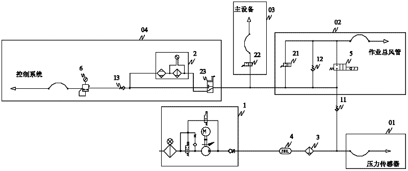

Image

  • Air source device
  • Air source device
  • Air source device

Examples


Embodiment 1

[0029] The invention provides a wind source device, such as figure 2 As shown, the air source device includes an air compressor 1, an air storage tank 4, a dryer 2, and a first filter 3. The air outlet of the air compressor 1 is connected to the air inlet of the air storage tank 4 through a pipeline, and the air storage tank 4 is output The gas port is connected to the air inlet of the first filter 3 through a pipeline, and the gas outlet of the first filter 3 is divided into a detection branch 01 and a gas supply main circuit, wherein the detection branch 01 provides a pressure detection interface for connecting a pressure sensor, and the gas supply The main road is equipped with a first one-way valve 11, and the air outlet of the first one-way valve 11 is respectively connected to the air supply branch 02 of the operation main air pipe, the air supply branch 03 of the main equipment and the air supply branch 04 of the control system; The gas supply branch 02 is composed of ...

Embodiment 2

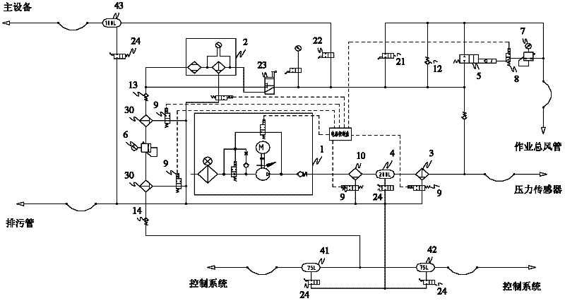
[0032] As a further improvement of the above embodiment, as image 3 As shown, on the basis of Embodiment 1, the wind source device of this embodiment also includes a first auxiliary air storage tank 41, a second auxiliary air storage tank 42 and a fourth one-way valve 14; wherein, the first auxiliary air storage tank The air inlet of the tank 41 and the air inlet of the second auxiliary air storage tank 42 are respectively connected to the air outlet of the fourth check valve 14, the air outlet of the first auxiliary air storage tank 41 and the outlet of the second auxiliary air storage tank 42. The air port is used to connect the air inlet of the control system respectively; the air inlet of the fourth one-way valve 14 is connected with the air outlet of the first decompression valve 6, and the air outlet of the fourth one-way valve 6 is respectively connected with the first auxiliary gas storage tank 41 and the first auxiliary air tank 41 Two auxiliary gas tanks 42.

[003...

Embodiment 3

[0037] Such as image 3 As shown, on the basis of the first or second embodiment above, the wind source device of this embodiment also includes a gas-water separator 10 for purifying the gas from the air compressor, and the gas-water separator 10 is further The air port is connected to the air outlet of the air compressor 1, and the air outlet of the gas-water separator 10 is connected to the air inlet of the air storage tank 4.


PUM


Abstract

The invention provides an air source device comprising an air compressor, an air storage tank, a dryer and a first filter, wherein an air outlet of the air compressor is sequentially connected with the air storage tank, the first filter and a first one-way valve in series by a pipeline, an air outlet of the first one-way valve is respectively connected with a detecting branch, an operating main air pipe air supplying branch, a main equipment air supplying branch and a control system air supplying branch; the operating main air pipe air supplying branch is formed by connecting a two-position two-way reversing valve, a second one-way valve and a second valve in parallel, the main equipment air supplying branch comprises a first valve, the control system air supplying branch comprises a two-position three-way valve, as well as the dryer, a third one-way valve and a pressure reducing valve which are connected in series by a pipeline, an air inlet of the two-position three-way valve is connected with the air outlet of the first one-way valve, and two air outlets of the two-position three-way valve are respectively connected an air inlet of the dryer and an air inlet of the third one-way valve. In the air source device, the multipath air supplying is realized and the technical problem in the prior art that air can not be continuously supplied in the prior art is solved.

Description

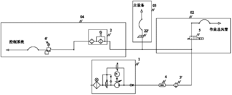
technical field [0001] The invention relates to an air source device, in particular to an air source device for providing multi-channel working air for a grinding vehicle. Background technique [0002] During the operation of the grinding car, uninterrupted and clean compressed air is required as the power source for the work of the grinding head and the driving source for the control system. [0003] At present, the air source device that supplies air to the grinding vehicle supplies air to the control system of the grinding vehicle, the main equipment (grinding head) and the main air duct of the working air through the air compressor 1 respectively. The air circuit diagram of the air source device is as follows figure 1 As shown, the air outlet of the air compressor 1 is connected in series with the air storage tank 4 and the filter 3' through the pipeline, and the pipeline connected to the air outlet of the filter 3' is divided into the main air duct air supply branch 02,...

Claims


Application Information

Patent Timeline
Patent Type & Authority Applications(China)
IPC IPC(8): B24B47/00
Inventor 张春潮孔德隆
Owner 太原中车时代轨道工程机械有限公司
Learn More