
Centrifugal pump

A centrifugal pump and pump body technology, applied in the field of centrifugal pumps, can solve the problems of accelerating the wear rate of particles on the outer wall of the box, waste of production resources, environmental pollution, etc., and achieve the effects of novel structure, extended service life and good sealing effect

Active Publication Date: 2013-04-10
SHANDONG SHUANGLUN
View PDF10 Cites 0 Cited by
  • Summary
  • Abstract
  • Description
  • Claims
  • Application Information

AI Technical Summary

Problems solved by technology

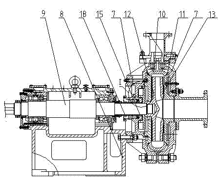
[0002] The existing centrifugal pump is composed of pump body, bracket body, pump shaft, inner pump casing, front liner, back liner, impeller, sealing packing device, and the pump shaft passes through bearing, bearing retaining sleeve, bearing sleeve cup and bearing The gland is fixedly connected with the bracket body, one end of the pump shaft is fixedly connected with the impeller through the sealing packing device, the impeller is set in the inner pump casing, the two ends of the inner pump casing are fixedly connected with the pump body through the lining plate, and the pump body is fixed on the bracket On the body, the seal packing device is composed of a stuffing box, a stuffing bushing, a stuffing ring, stuffing and a stuffing gland. The cavity of the stuffing box is provided with an auxiliary impeller, and the auxiliary impeller is fixed on the pump shaft. The outer end of the stuffing box is connected to the The rear liner is sealed and connected, the other end is fixedly connected with the pump body, and the inner circle is fixedly connected with the pump shaft through the packing sleeve. The packing ring, packing and packing gland are set on the packing sleeve to make the centrifugal pump work normally. The ring river packing acts as a seal to ensure that the liquid in the pump body does not leak out, avoiding waste and pollution. Since the packing of the sealed stuffing box is oil-sand line, the wear resistance is relatively poor. When the transported medium particles enter the sealed stuffing box , driven by the high-speed operation of the pump, the solution in the sealed stuffing box is in a high-speed operation state, which accelerates the wear rate of the particles on the outer wall of the box, causing the liquid in the pump to flow out, which in turn causes environmental pollution and waste. Therefore, it is necessary to stop the pump to The replacement of the stuffing of the sealed stuffing box will have a great impact on production and waste a lot of resources. If the stuffing seal is too tight, the load will be increased, and the stuffing will heat up quickly, which will damage the pump shaft. If it is enlarged, it needs to be replaced frequently, but if it is pressed too loosely, it will flow into the air and cause it to be unusable. All parts other than the ring are disassembled, and even the pump or motor has to be disassembled, which brings great inconvenience to the customer to replace the packing ring, and makes it difficult to install during assembly, resulting in a waste of working time and greatly improved work efficiency. decline

Method used


Image

  • Centrifugal pump
  • Centrifugal pump
  • Centrifugal pump

Examples


Embodiment Construction

[0015] Below in conjunction with accompanying drawing, the present invention is further described:

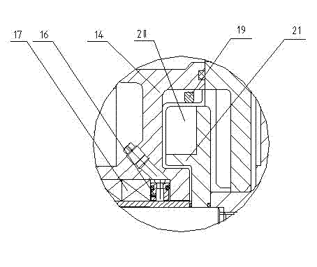
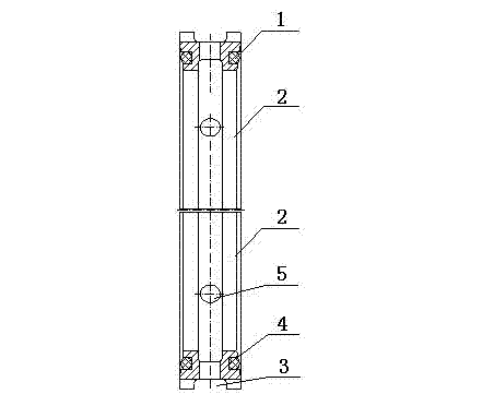
[0016] As shown in the drawings, a centrifugal pump is equipped with a pump body 7, a bracket body 8, a pump shaft 9, an inner pump casing 10, a front liner 11, a rear liner 12, an impeller 13, a sealing packing device, and a sealing packing The device is composed of stuffing box 14, stuffing bushing 15, stuffing ring 16, stuffing 17 and stuffing gland 18. The cavity of stuffing box 14 is provided with auxiliary impeller 20, pump body 7, bracket body 8, pump shaft 9, inner The connection relationship of the pump casing 10, the front liner 11, the rear liner 12, the impeller 13, the stuffing box 14, the stuffing sleeve 15, the stuffing ring 16, the stuffing 17 and the stuffing gland 18 is the same as that of the prior art, and will not be repeated here. It is characterized in that there is an O-ring 1, and the packing ring 16 is composed of at least two packing ring bodies 2. Th...


PUM


Abstract

The invention relates to the technical field of fluid machinery, particularly relates to a centrifugal pump. The centrifugal pump comprises a pump body, a bracket body, a pump shaft, an inner pump case, a front lining plate, a back lining plate, an impeller and a sealing packing device, wherein the sealing packing device is composed of a packing box, a packing shaft sleeve, a packing ring, packing and a packing gland. The centrifugal pump is characterized in that an O-shaped ring is arranged; the packing ring is formed by splicing at least two packing ring bodies together; the packing ring bodies are of ring shapes; the outside circumference of the packing ring body is provided with a positioning groove, and two ends of the packing ring body are respectively provided with annular grooves;the packing ring bodies are provided with water inlet holes in the radial direction; the water inlet holes are communicated with the positioning grooves; the interior of the annular groove is provided with disassembled screw holes; the O-shaped ring is fastened in the annular grooves on the two ends of the packing ring bodies and pieces the packing ring bodies to the packing ring; and the inner wall of the cavity of the sealing packing box is provided with a blocking ribbed plate. By adopting the structure, the centrifugal pump provided by the invention has the advantages of novel structure, good sealing effect and high stability, is convenient for disassembling and is rapid to install, abrasion rate is reduced, the service life is prolonged, and the like.

Description

technical field [0001] The invention relates to the technical field of fluid machinery, in particular to a centrifugal pump which is easy to assemble and disassemble and wear-resistant. Background technique [0002] The existing centrifugal pump is composed of pump body, bracket body, pump shaft, inner pump casing, front liner, back liner, impeller, sealing packing device, and the pump shaft passes through bearing, bearing retaining sleeve, bearing sleeve cup and bearing The gland is fixedly connected with the bracket body, one end of the pump shaft is fixedly connected with the impeller through the sealing packing device, the impeller is set in the inner pump casing, the two ends of the inner pump casing are fixedly connected with the pump body through the lining plate, and the pump body is fixed on the bracket On the body, the seal packing device is composed of a stuffing box, a stuffing bushing, a stuffing ring, stuffing and a stuffing gland. The cavity of the stuffing bo...

Claims


Application Information

Patent Timeline
Patent Type & Authority Patents(China)
IPC IPC(8): F04D29/08F04D29/22
Inventor 于泳水林海韩旭
Owner SHANDONG SHUANGLUN
Learn More