
Oil-guiding device for oil pressure brake

An oil guide device and oil pressure technology, which is applied in the field of hydraulic brake oil guide devices, can solve problems such as brake failure, endanger the rider's own safety, affect the braking effect, etc., and achieve the effect of prolonging the service life and good braking effect

Inactive Publication Date: 2012-03-14
ASHIMA LTD
View PDF6 Cites 2 Cited by
  • Summary
  • Abstract
  • Description
  • Claims
  • Application Information

AI Technical Summary

Problems solved by technology

[0005] However, this installation method will cause the oil chamber seat to be inclined on the handlebar, and the oil in the lower oil chamber that has been used for a long time will flow to the brake caliper through the oil pipe to accumulate excess oil, resulting in insufficient oil in the oil tank. Air enters the oil circuit through the oil guide hole, causing air pressure and air bubbles, which not only affect the braking effect, but too many air bubbles in the oil circuit will seriously cause brake failure, and endanger the rider's own safety

Method used


Image

  • Oil-guiding device for oil pressure brake
  • Oil-guiding device for oil pressure brake
  • Oil-guiding device for oil pressure brake

Examples


Embodiment Construction

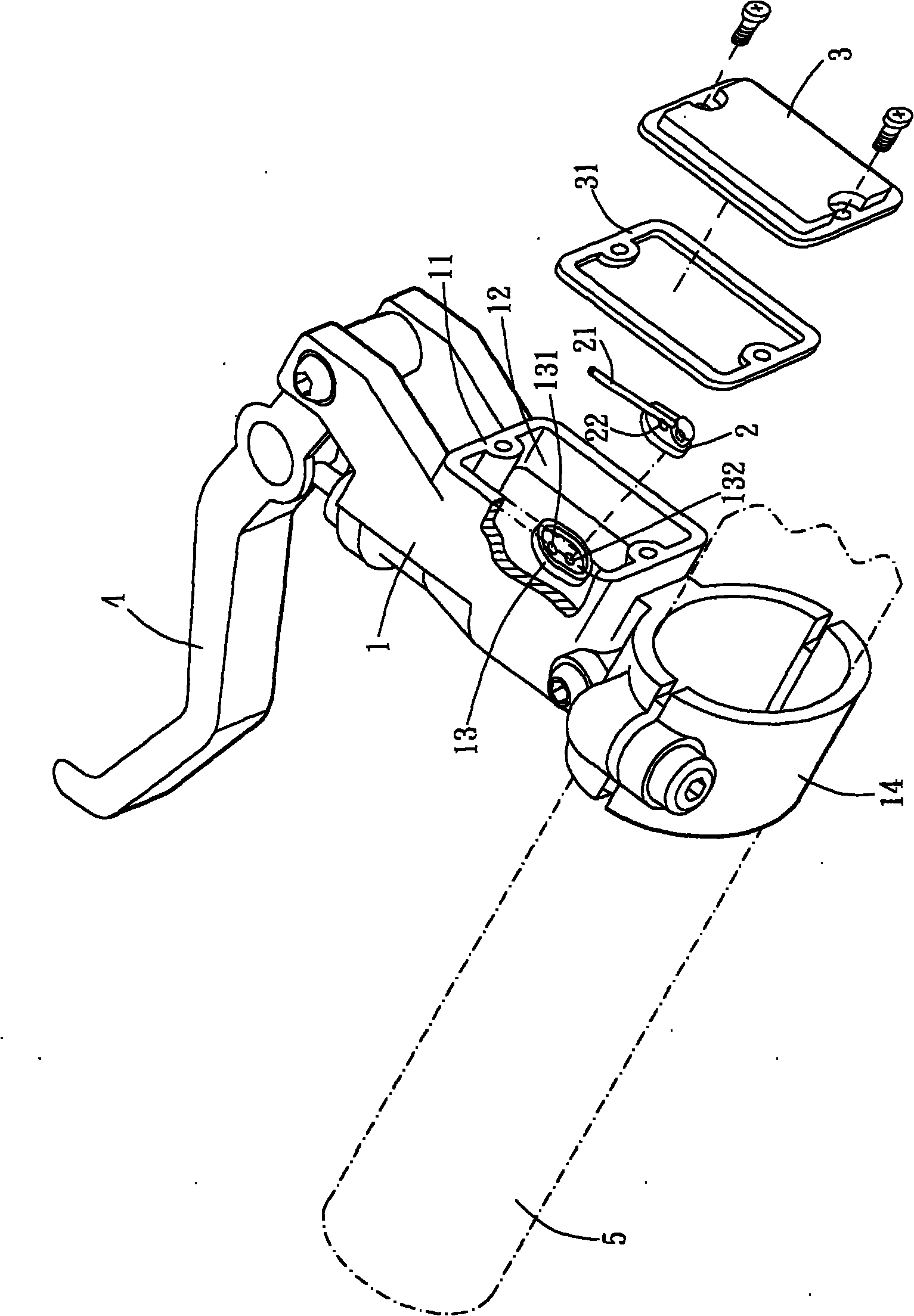
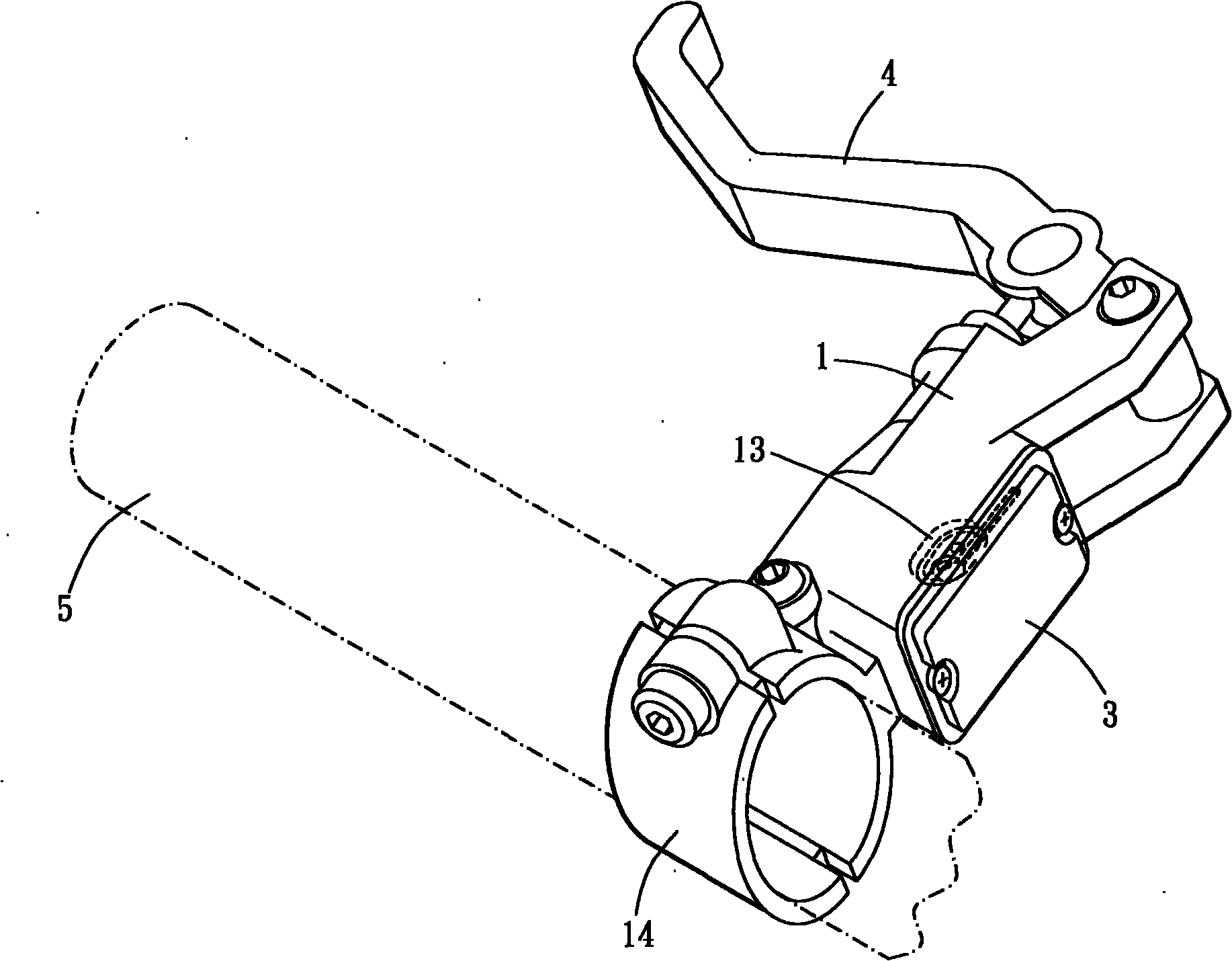
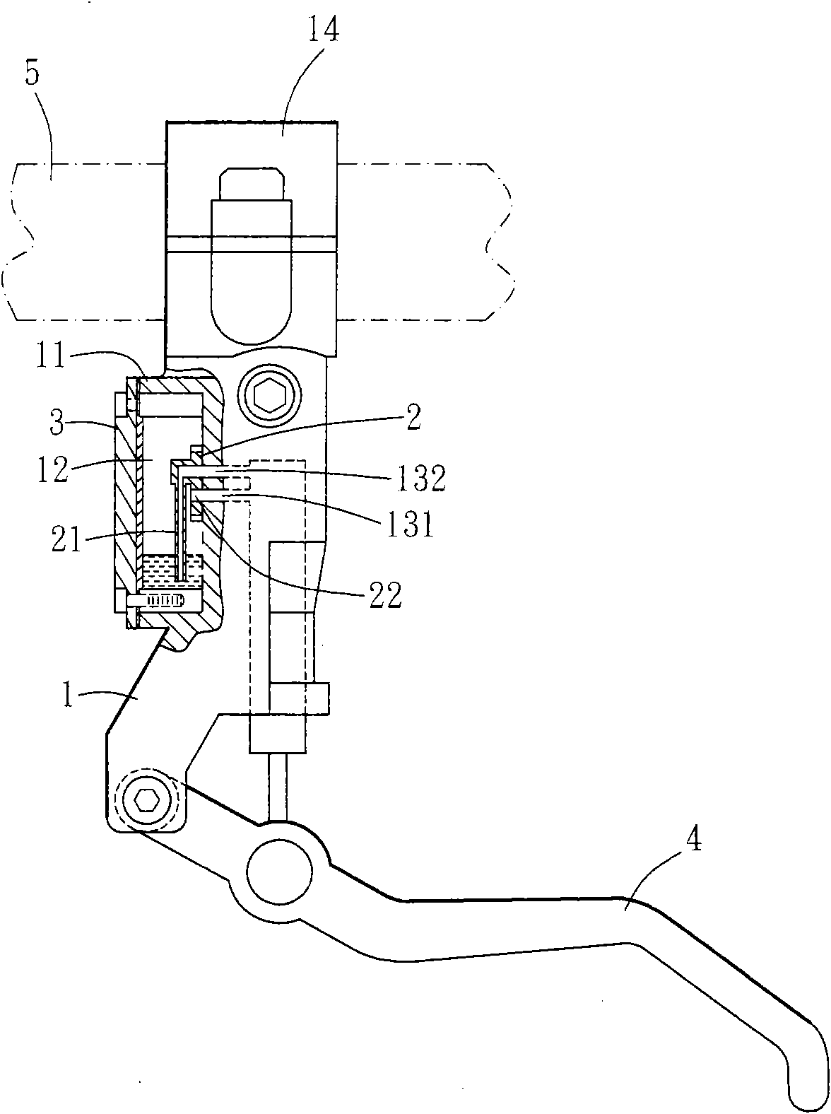
[0023] see figure 1 and figure 2 As shown, it is the main embodiment of the present invention, including a brake handle 1, an oil guide 2 and a cover plate 3, wherein:

[0024] The brake handle 1 is provided with an oil storage seat 11, the oil storage seat 11 is an oil chamber 12, the bottom of the oil chamber 12 is provided with an oil guide seat 13, and the oil guide seat 13 is provided with an oil inlet hole 131 and an oil outlet Oil hole 132, such as figure 1 As shown, one end of the brake handle 1 is pivotally engaged with the brake lever 4 of the bicycle, and the oil storage seat 11 is provided on the brake handle 1. The oil storage seat 11 is a hollow oil chamber 12, and the bottom of the oil chamber 12 is The erected oil guide seat 13 is established, and the oil inlet hole 131 and the oil outlet hole 132 are arranged on the inner surface of the oil guide seat 13, and the other end of the brake handle 1 pivotally provided with the brake lever 4 is provided with a jo...


PUM


Abstract

The invention relates to an oil-guiding device for an oil pressure brake, which comprises a brake handle, an oil-guiding piece and a cover plate, wherein an oil storage base is arranged on the brake handle; an oil chamber is arranged in the oil storage base; an oil-guiding base is arranged at the bottom of the oil chamber; an oil inlet and an oil outlet are formed on the oil-guiding base; the oil-guiding piece is combined with the oil-guiding base; an oil pipe opposite to the oil outlet and an oil hole opposite to the oil inlet are arranged on the oil-guiding piece; an end part of the oil pipe faces to a position of a joint of the brake handle and a brake bar; and the cover plate is jointed outside the oil storage base and is used for sealing the oil chamber. When the brake handle is in bias arrangement relative to a bicycle handle, oil materials in the oil chamber are accumulated at one end of the oil chamber close to the brake bar under the action of gravity, the oil materials on the end part of the oil chamber are absorbed by the oil pipe and are output from the oil outlet for braking, and the recycled oil materials are received by the oil inlet so as to enter into the oil chamber, thereby avoiding causing phenomena of air bubbles and air compression and keeping normal running of the brake.

Description

technical field [0001] The invention relates to a hydraulic brake oil guiding device. Background technique [0002] The brake system on the bicycle is the key to control the speed of the vehicle and maintain safety. In the brake system, such as the hydraulic disc brake system, it is mainly equipped with an oil chamber seat with built-in oil on the handlebar. One end is provided with a brake handle that can be used for pulling, and the other end of the oil chamber seat is provided with an oil pipe connected to the brake caliper, so that when the user presses the brake handle, the oil in the oil chamber seat can be squeezed into the oil pipe , and then push the pad in the brake caliper to clamp the disc on the wheel to achieve the purpose of braking. The hydraulic brake system can greatly improve its anti-wear ability through the characteristics of high oil viscosity without arbitrary pressure reduction, and it is easy to maintain balance to improve its braking effect, so it ...

Claims


Application Information

Patent Timeline
IPC IPC(8): B62L3/02B60T17/04
Inventor 莫韦恩
Owner ASHIMA LTD
Learn More