
Flat plate type redox flow battery

A flow battery, configuration-type technology, applied in fuel cell additives, indirect fuel cells, etc., can solve problems such as increased power consumption, battery cell leakage, and increased electrolyte circulation pump infusion resistance, reducing Liquid junction current, the effect of increasing degrees of freedom

Inactive Publication Date: 2012-02-29
上海裕豪机电有限公司 +1
View PDF4 Cites 4 Cited by
  • Summary
  • Abstract
  • Description
  • Claims
  • Application Information

AI Technical Summary

Problems solved by technology

[0006] In order to control the combined current of this liquid to a minimum, the method of making the diameter of the infusion tube thinner or longer is adopted, but the disadvantage of these methods is that it will increase the infusion resistance of the electrolyte circulation pump and increase the overall power consumption. volume increase
[0007] In addition, due to the possibility of liquid leakage due to the multi-layer stacking of battery cells, it is necessary to take countermeasures to periodically tighten the screws

Method used


Image

  • Flat plate type redox flow battery
  • Flat plate type redox flow battery
  • Flat plate type redox flow battery

Examples


Embodiment Construction

[0022] The preferred embodiments of the present invention are given below in conjunction with the accompanying drawings to describe the technical solution of the present invention in detail.

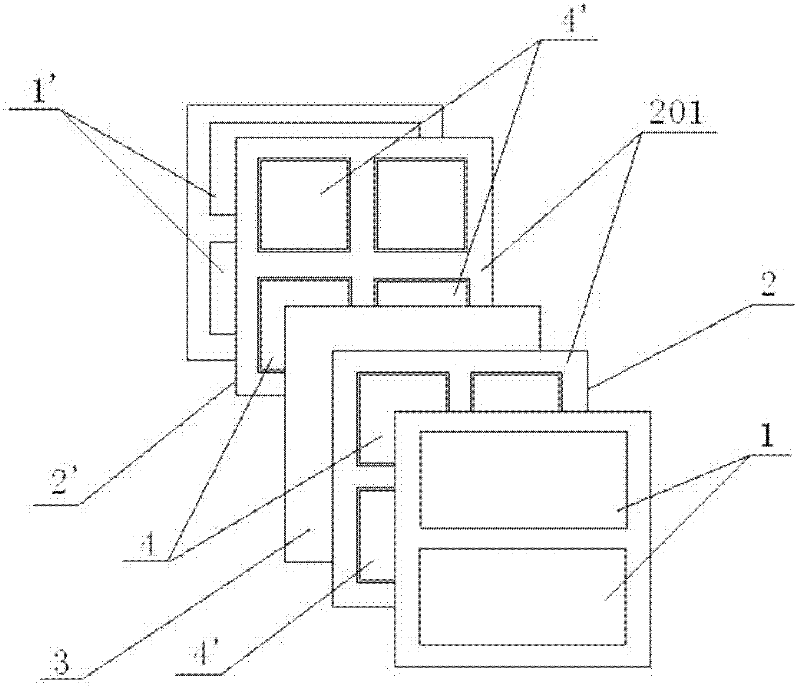
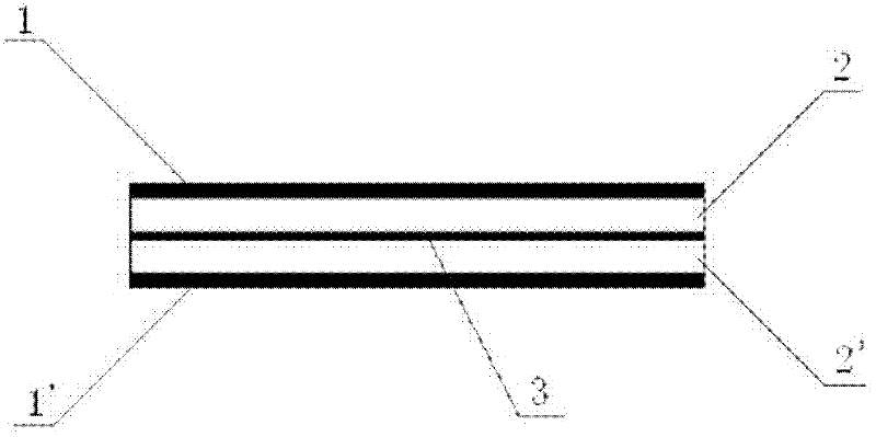
[0023] Such as figure 1 and figure 2 As shown, a redox flow battery with a flat plate configuration includes an electrolytic cell, a reaction electrode, a power supply electrode and a separation membrane, and is characterized in that, from top to bottom, the upper power supply electrode 1, the upper side electrolytic cell 2, and the separation membrane are sequentially separated. The membrane 3, the lower electrolytic cell 2' and the lower power supply electrode 1' are stacked. The electrolytic cells 2, 2' are separated into four electrolytic chambers arranged in a square shape by the electrolytic frame 201. In the upper electrolytic cell 2 Two pairs of positive reaction electrodes 4 and negative reaction electrodes 4' are arranged crosswise in the four electrolytic chambers, and two p...


PUM


Abstract

The invention provides a flat plate type redox flow battery, which comprises electrolyzers, a reaction electrode, power supply electrodes and a separating membrane and is characterized by being formed by stacking an upper side power supply electrode, an upper side electrolyzer, the separating membrane, a lower side electrolyzer and a lower side power supply electrode sequentially from top to bottom, wherein each electrolyzer is divided into four electrolytic chambers which are arranged into a shape like Chinese character 'TIAN' by an electrolytic frame; two pairs of positive reaction electrodes and negative reaction electrodes are arranged in the four electrolytic cambers of the upper side electrolyzer in a crossed manner; two pairs of positive reaction electrodes and negative reaction electrodes of which the polarities are opposite to the polarities of a corresponding position of the upper side electrolyzer are arranged in the lower side electrolyzer; the positive reaction electrodesand the negative reaction electrodes are contacted with the power supply electrodes respectively and connected in series with one another according to the opposite polarities so as to form a circuit;and the electrolytic chambers in the electrolyzers are connected with one another through pipelines according to the same polarity. In the invention, battery units are arranged in a manner of a flat plate, so liquid complexing current can be reduced, the reliability of the battery is improved and the free degree of the arrangement is increased.

Description

technical field [0001] The present invention relates to a redox flow battery, in particular to a structure of a flat-plate redox flow battery. Background technique [0002] Generally, redox flow batteries have generally adopted a method of stacking battery cells in series to obtain the required voltage. However, due to the low electromotive force of each battery cell in redox flow batteries, it is necessary to allow It is best to use interlayer bipolar plates for electrolyte circulation. [0003] The most important thing in this method is the solution of liquid junction and liquid leakage. [0004] The so-called liquid junction means that there is a potential difference between the electrolyte solution flowing into or out of the battery cell and other battery cells, so that the current is short-circuited through the electrolyte solution. [0005] For example, when 40 battery cells are connected in series, the potential difference generated in the initial stage of the stack...

Claims


Application Information

Patent Timeline
Patent Type & Authority Applications(China)
IPC IPC(8): H01M8/04H01M8/20
CPCY02E60/50
Inventor 高村孝次
Owner 上海裕豪机电有限公司
Learn More