
Device and method for testing wind pressure on surface of building structure

A technology for testing devices and building structures, applied in the testing of machines/structural components, measuring devices, aerodynamic tests, etc., can solve problems such as distortion, and achieve the effects of light weight, good portability, and high testing accuracy

Inactive Publication Date: 2012-02-22
HUNAN UNIV
View PDF6 Cites 21 Cited by
  • Summary
  • Abstract
  • Description
  • Claims
  • Application Information

AI Technical Summary

Problems solved by technology

[0003] The purpose of the present invention is to overcome the limitations and distortions of existing wind pressure testing methods under strong wind and rain weather conditions, and provide a wind pressure on the surface of building structures with simple testing principles, high testing accuracy, good frequency response characteristics, and good stability. The test device can be widely used in wind pressure tests on the surface of building structures under strong wind and rain (such as typhoon) weather conditions

Method used


Image

  • Device and method for testing wind pressure on surface of building structure
  • Device and method for testing wind pressure on surface of building structure
  • Device and method for testing wind pressure on surface of building structure

Examples


Embodiment 1

[0017] Embodiment 1: with reference to accompanying drawing:

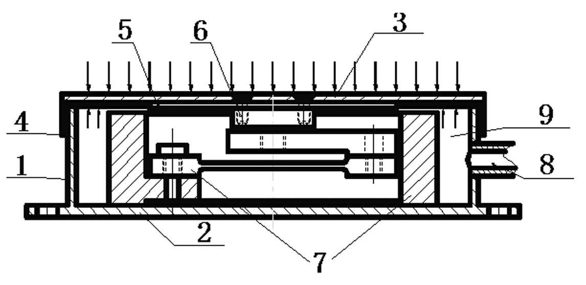
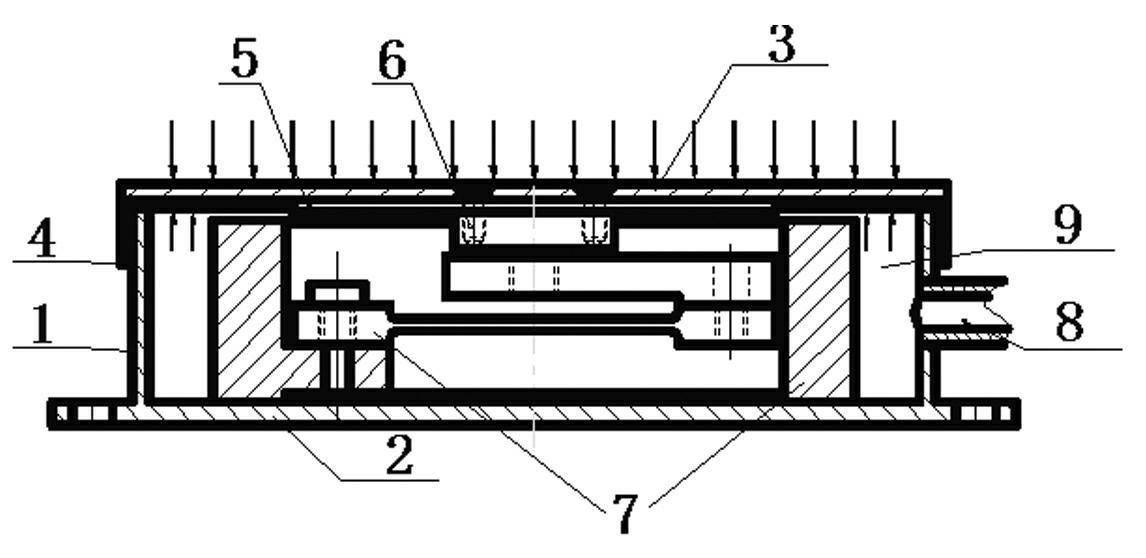
[0018] In this embodiment, a cylindrical shell with a diameter of 100 mm and a height of 26 mm is provided, and its lower part and a chassis 2 with a diameter of 120 mm and a thickness of 2 to 3 mm are machined to form a thin-walled cavity cylinder 1 . The upper part of the cavity cylinder body 1 is provided with a disc-shaped load-bearing panel 3 with a diameter of 100 mm and a thickness of 2 mm, and the lower end of the disc-shaped load-bearing panel 3 covers the cavity cylinder body through a sealing structure 4; they together form a Thin wall cavity box. A miniature force sensor 7 with a height of 20mm-25mm and a beam structure is arranged in the thin-walled cavity box. The upper part of the miniature force sensor 7 is connected with the balance disc 5 , and the lower part is fixedly connected with the chassis 2 . A hole tube 8 with a diameter of 6mm is provided on the side of the thin-walled cavity box. The ...

Embodiment 2

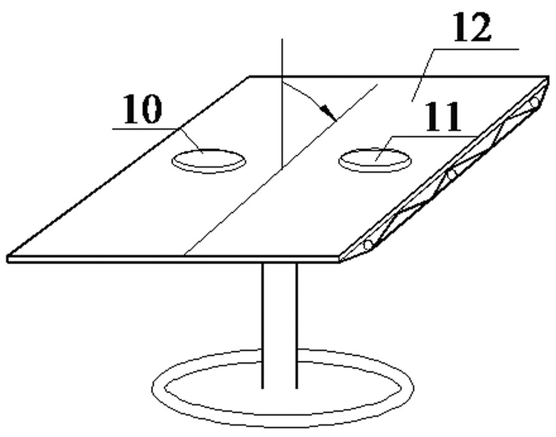
[0022] (1) Calibrate the test accuracy of the wind pressure test device; according to the wind tunnel pressure test of the 1:1 rigid model in the prior art, it is determined that the wind pressure test device tests the wind pressure and the incoming wind speed pressure under different elevation angle conditions corresponding relationship. In the wind tunnel test, first design a flat support 12 that can rotate freely in the vertical direction, and its elevation angle can vary from 0 to 90 degrees when rotating; on the flat support 12, a wind pressure test device 10 and a rigidity of 1:1 are symmetrically arranged. Model 11, the pressure measuring points of the shown rigid model 11 are arranged at an angle of 15 degrees and in 8 equal parts along the diameter direction. According to the results of the wind tunnel pressure test, the test accuracy of the wind pressure test device is calibrated, and the corresponding relationship between the wind pressure tested by the wind pressur...


PUM

PropertyMeasurementUnit
Diameteraaaaaaaaaa
Wall thicknessaaaaaaaaaa
Heightaaaaaaaaaa

Abstract

The invention discloses a device and method for testing wind pressure on the surface of a building structure. The device is provided with a thin wall cavity box body formed by a thin wall shell, a chassis and a load-bearing panel through sealing, a micro force sensor is arranged in the thin wall cavity box body, the upper part of the micro force sensor is connected with a balance disk through a connecting member and the lower part of the micro force sensor is fixed with the chassis, and the side surface of the cavity box body is provided with a pipeline communicated with a reference pressure system. During the measurement, the chassis is fixed on the surface of the building structure, incoming flow wind speed pressure acts on the upper surface of the load-bearing panel, a guide hole pipeline is communicated with an external reference pressure to form a reference internal pressure to act on the lower surface of the load-bearing panel, the pressure difference of the load-bearing panel is converted into concentrated force through the balance disk, the concentrated force is transferred to a pull pressure sensor through a connecting member, and the force measured by the pull pressure sensor corresponds to the internal and external pressure difference. The invention has the advantages of high testing accuracy, frequency response characteristic and better stability, and can be widely applied to a prototyping computer pilot of the wind pressure on the surface of the building structure under an extreme climate condition.

Description

technical field [0001] The invention relates to a wind pressure test device and a test method for the surface of a building structure. Background technique [0002] Existing wind tunnel tests of building structure models often require the use of relatively large scale models. However, due to the limitation of the cross-sectional area of ​​the wind tunnel and the wind speed, the Reynolds model law in the boundary layer of the wind tunnel is not satisfied, which affects whether the wind tunnel test of the building structure model It can truly and accurately reflect the wind load of the actual building structure. The prototype measurement of wind pressure on the building surface is an extremely important way to solve this problem, and it provides a benchmark and verification for the existing wind tunnel test simulation methods and methods. The existing wind pressure measurement method is to open holes on the surface of the building structure, design the pipeline system, and us...

Claims


Application Information

Patent Timeline
IPC IPC(8): G01M9/06
Inventor 胡尚瑜李秋胜
Owner HUNAN UNIV
Learn More