Electric cabinet cover plate

A technology of electric control box and cover plate, applied in electrical components, substation/switch layout details, cooling/ventilation of substation/switchgear, etc.

Inactive Publication Date: 2012-02-22
SANY HEAVY EQUIP
View PDF6 Cites 3 Cited by
  • Summary
  • Abstract
  • Description
  • Claims
  • Application Information

AI Technical Summary

Problems solved by technology

[0006] However, although figure 1 The cover plate structure of the electric control box shown in can meet the basic cooling and heat dissipation needs of the electric control box, but after the water tank 12 is processed on the surface of the cover plate 11 of the electric control box, the water tank of the cover plate 11 of the electric control box will The thickness of one side of part of the board is reduced, the overall structure of the electric control box cover 11 is unevenly stressed, the structural strength is reduced, and deformation and damage are easily generated during use

Method used


Image

  • Electric cabinet cover plate
  • Electric cabinet cover plate
  • Electric cabinet cover plate

Examples


Embodiment Construction

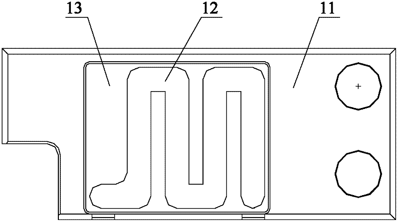
[0023] The core of the present invention is to provide a cover plate of the electric control box, the structure strength of the cover plate of the electric control box is relatively high.

[0024] In order to enable those skilled in the art to better understand the solution of the present invention, the present invention will be further described in detail below in conjunction with the accompanying drawings and specific embodiments.

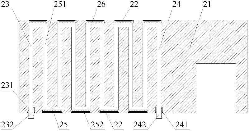
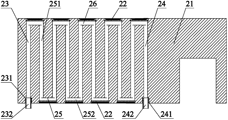
[0025] Please refer to figure 2 , figure 2 It is a schematic cross-sectional structure diagram of an electric control box cover provided by a specific embodiment of the present invention.

[0026] In a specific embodiment, the cover plate of the electric control box provided by the present invention has a plurality of through holes 23 inside, the extending direction of the through holes 23 is consistent with the width direction of the cover plate 21 of the electric control box, and each through hole 23 is along the The length direction of the...


PUM


Abstract

The invention discloses an electric cabinet cover plate. The electric cabinet cover plate is characterized in that internal through holes of the electric cabinet cover plate are cooperated and communicated with water tanks and sealing plates are installed on the water tanks so that the interior of the electric cabinet cover plate forms a coiled pipe where water flowing and thus overall cooling performances of the electric cabinet cover plate are guaranteed; the whole coiled pipe is arranged in the electric cabinet cover plate and a structure which belongs to the electric cabinet cover plate and is arranged in a thickness direction is symmetrical relatively so that stress distribution is even and thus structure strength of the electric cabinet cover plate is improved and deformation and damage is difficult to be produced in production; and a water channel arranged in an outer surface of the electric cabinet cover plate is not needed so that the electric cabinet cover plate does not need large processing thickness and in assembling, a cover panel which matches with the water channel and is arranged in the outer surface of the electric cabinet cover plate is not needed and thus the thickness of the electric cabinet cover plate is reduced relatively.

Description

technical field [0001] The invention relates to the technical field of coal mining machinery, in particular to a cover plate of an electric control box. Background technique [0002] As a common mining machine, coal shearer is widely used in all aspects of energy mining. As an important part of the shearer, the electric control box is the core component that controls the entire shearer. With the continuous improvement of production intensity, people have put forward higher requirements for the performance of electric control boxes. [0003] Since the heating phenomenon of the electrical components inside the electric control box during the working process will seriously affect the performance of the electrical components themselves and related components, heat dissipation is an essential performance of the electric control box. [0004] Please refer to figure 1 , figure 1 It is a structural schematic diagram of the electric control box cover part of a typical shearer in ...

Claims


Application Information

Patent Timeline
Patent Type & Authority Applications(China)
IPC IPC(8): E21C35/00H02B1/46H02B1/56
Inventor 刘丹张祚明刘磊马庆良
Owner SANY HEAVY EQUIP
Why Eureka
Try Eureka