Water saving gate used for supplying power to flow sensor and provided with wind energy generating system

A wind power generation system and flow sensor technology, applied in irrigation pipelines, applications, buildings, etc., can solve problems such as outdated gates, failure to manage well, waste of water resources, etc.

Inactive Publication Date: 2012-02-22
WUXI TONGCHUN NEW ENERGY TECH
View PDF6 Cites 4 Cited by
  • Summary
  • Abstract
  • Description
  • Claims
  • Application Information

AI Technical Summary

Problems solved by technology

On the farm, due to the outdated, crude and poor management of the gates, there is still a lot of waste of water resources

Method used


Image

  • Water saving gate used for supplying power to flow sensor and provided with wind energy generating system
  • Water saving gate used for supplying power to flow sensor and provided with wind energy generating system

Examples


Embodiment 1

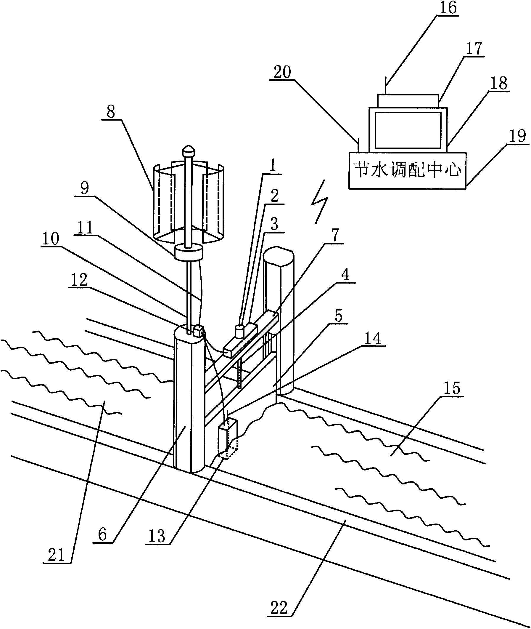
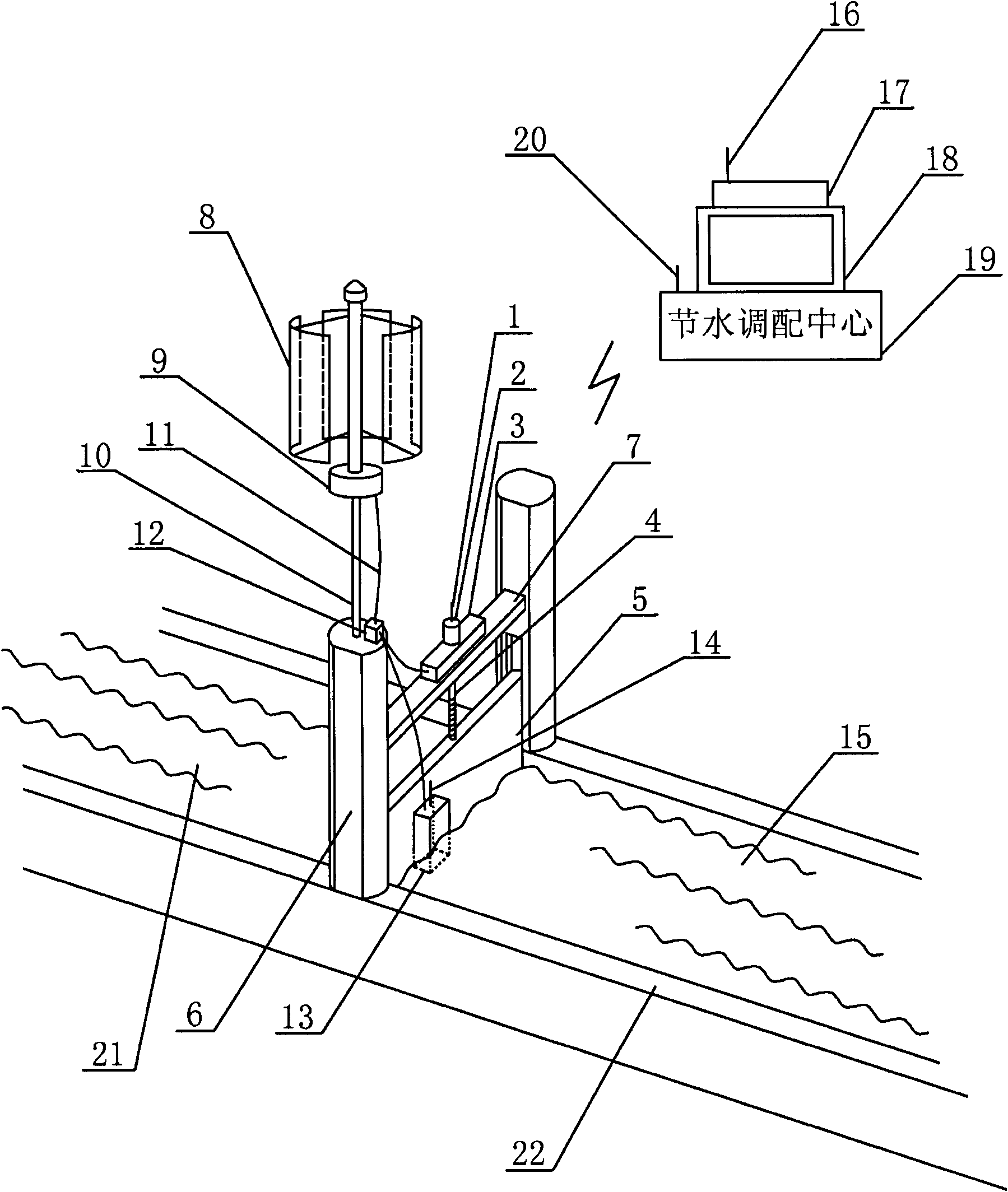
[0023]The current output by the vertical axis wind turbine is input into the shunt through the conductive wire, and the current output from the shunt is input into the motor and the Hall flow sensor through the conductive wire to provide working power. The Hall flow sensor senses the change of the water flow and converts it into an electrical signal. The transmitting antenna A installed on the Hall flow sensor sends the electrical signal to the air. After receiving the electrical signal, the receiving antenna B of the water-saving allocation center inputs The computer processor B combines the water demand data of the paddy fields to process and obtain a water-saving plan. After the scientific and technical personnel confirm the water-saving plan on the monitor, the transmitting antenna B installed on the water-saving allocation center sends out a water supply command, which is installed on the irrigation sluice After receiving the electrical signal, the receiving antenna A rece...

Embodiment 2

[0025] The current output by the horizontal axis wind turbine is input into the shunt through the conductive wire, and the current output from the shunt is input into the motor and the liquid turbine flow sensor through the conductive wire to provide working power. The liquid turbine flow sensor senses the change of water flow and converts it into an electrical signal. The transmitting antenna A installed on the liquid turbine flow sensor sends the electrical signal to the air. After receiving the electrical signal, the receiving antenna B of the water-saving allocation center inputs The computer processor B combines the water demand data of the paddy fields to process and obtain a water-saving plan. After the scientific and technical personnel confirm the water-saving plan on the monitor, the transmitting antenna B installed on the water-saving allocation center sends out a water supply command, which is installed on the irrigation sluice After receiving the electrical signal,...


PUM


Abstract

The invention relates to a water saving gate used for supplying power to a flow sensor and provided with a wind energy generating system, belonging to the technical field of new energy networking applications. A current output by a wind driven generator is input into a shunt by virtue of a conductor wire, and the current output by the shunt is input into a motor and the flow sensor by virtue of a conductor wire to provide working electricity. The flow sensor senses variation of water body flow and converts the variation into an electric signal, a transmitting antenna I arranged on the flow sensor transmits the electric signal into the air, after a receiving antenna II of a water saving dispatching center receives the electric signal, the electric signal is input into a computer processor II to be processed by combining with rice field water demand data to obtain a water saving scheme, a technician confirms the water saving scheme on a display, a transmitting antenna II arranged on the water saving dispatching center sends out a water supply instruction, after a receiving antenna I arranged on an irrigation water gate receives the electric signal, the electric signal is input into a computer processor I to be processed, the motor is regulated to lift a gate and drain off according to the water saving scheme, and water irrigation is carried out.

Description

technical field [0001] The invention relates to a water-saving gate with a wind power generation system supplying power to a flow sensor, and belongs to the technical field of new energy Internet of Things applications. Background technique [0002] 70.8% of the earth's surface is covered by water, and salt water accounts for 97.5% of all water resources. Human beings cannot drink salt water, nor can they use salt water to irrigate crops such as rice and corn. Fresh water resources account for only 2.5% of all water resources, and ice and snow in the north and south polar ice caps, alpine glaciers and permafrost zones account for 87% of the 2.5% of total fresh water resources. The fresh water resources that humans can actually use only account for 0.26% of the total water on the earth, mainly rivers, lakes and a part of groundwater. The distribution of fresh water resources in the world is uneven. Most of the fresh water resources are concentrated in 10 countries, and 80 co...

Claims


Application Information

Patent Timeline
IPC IPC(8): E02B13/02
Inventor 缪同春
Owner WUXI TONGCHUN NEW ENERGY TECH
Why Eureka
Try Eureka