
Rubber pipe molding mold and rubber pipe molding method

A technology for molding molds and molding methods, which is applied to household appliances, tubular objects, and other household appliances, and can solve problems such as non-recyclable, waste of resources, and environmental pollution caused by raw materials, and achieve the effect of avoiding waste of resources and environmental pollution

Active Publication Date: 2012-02-22
ANHUI ZHONGDING HOSE PROD
View PDF7 Cites 9 Cited by
  • Summary
  • Abstract
  • Description
  • Claims
  • Application Information

AI Technical Summary

Problems solved by technology

Obviously, in order to meet the application requirements of the rubber tube, a certain amount of margin is cut at both ends, which is a serious waste of resources, which greatly increases the processing cost of the rubber tube
On the other hand, rubber materials are generally not recyclable after being treated by vulcanization process, so the cut material ends can cause serious pollution to the environment

Method used


Image

  • Rubber pipe molding mold and rubber pipe molding method
  • Rubber pipe molding mold and rubber pipe molding method
  • Rubber pipe molding mold and rubber pipe molding method

Examples


Embodiment Construction

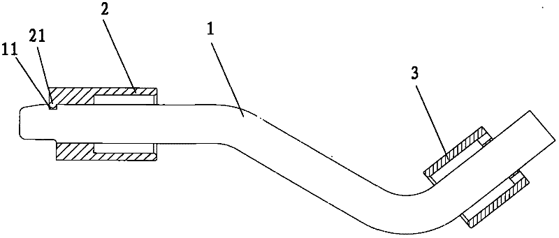
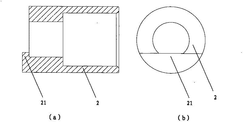
[0023] like figure 1 As shown, it is a schematic structural diagram of a rubber tube forming mold proposed by the present invention. Referring to the drawings, a rubber tube forming mold proposed by the present invention includes a forming core 1, a first positioning sleeve 2 and a second positioning sleeve 3, and the inner holes of the first positioning sleeve 2 and the second positioning sleeve 3 are steps The first positioning sleeve 2 is detachably sleeved on the upper end of the forming mold core 1, and the second positioning sleeve 3 is fixedly sleeved on the lower end of the forming mold core 1 by welding or screw connection. It should be noted that, the first positioning sleeve 2 is detachably sleeved on the forming die core 1 to ensure the operability of the rubber tube forming die.

[0024] The relative position between the first positioning sleeve 2 and the forming mold core 1 is fixed, which ensures that the first positioning sleeve 2 and the forming mold core 1 w...


PUM


Abstract

The invention discloses a rubber pipe molding mold and a rubber pipe molding method. The rubber pipe molding mold comprises a molding mold core (1), a first positioning sleeve (2) and a second positioning sleeve (3), wherein the first positioning sleeve (2) is detachably sleeved at the upper end of the molding mold core (1), the relative position between the first positioning sleeve (2) and the molding mold core (1) is fixed, the second positioning sleeve (3) is fixedly sleeved at the lower end of the molding mold core (1), and a through hole is processed on the second positioning sleeve (3). By means of the rubber pipe molding mold, the parameters of two ends of the molded rubber pipe meet requirements of industrial application, and resource waste and environment pollution caused by the cutting mode in the prior art are avoided.

Description

technical field [0001] The invention relates to the technical field of rubber tube forming, in particular to a rubber tube forming die and a rubber tube forming method. Background technique [0002] Rubber tubes are more and more widely used in industrial scenarios. For example, special-shaped rubber tubes are one of the most widely used parts in the automotive field. In the prior art, the special-shaped rubber tube is generally processed and manufactured by the mandrel vulcanization molding process. After the rubber tube is processed and formed, in order to ensure the flatness of both ends of the rubber tube and the appropriate assembly length, it is often necessary to cut the rubber tube at both ends. way to remove the 10mm-30mm margin. Obviously, cutting a certain amount of margin at both ends of the rubber tube in order to meet the application requirements of the rubber tube is a serious waste of resources, which greatly increases the processing cost of the rubber tube....

Claims


Application Information

Patent Timeline
Patent Type & Authority Applications(China)
IPC IPC(8): B29C35/00B29L23/00
Inventor 韦文高夏迎松朱宝宁李雪芸
Owner ANHUI ZHONGDING HOSE PROD
Learn More