
Automatic feeding heat energy garbage treatment machine

A technology of automatic feeding and garbage disposal, which is applied to the removal of solid waste, etc., can solve problems such as inconsistency of scientific and technological concepts, inability to automatically feed materials, and crude feeding units, and achieve the effects of simple and reliable structure, slow feeding, and optimized structure

Inactive Publication Date: 2012-02-22
陈树华
View PDF4 Cites 0 Cited by
  • Summary
  • Abstract
  • Description
  • Claims
  • Application Information

AI Technical Summary

Problems solved by technology

However, the feeding unit of the existing heat energy waste disposer is too simple and cannot be fed automatically, which requires a lot of manpower and does not conform to the scientific and technological concept of automatic production

Method used


Image

  • Automatic feeding heat energy garbage treatment machine
  • Automatic feeding heat energy garbage treatment machine

Examples


Embodiment Construction

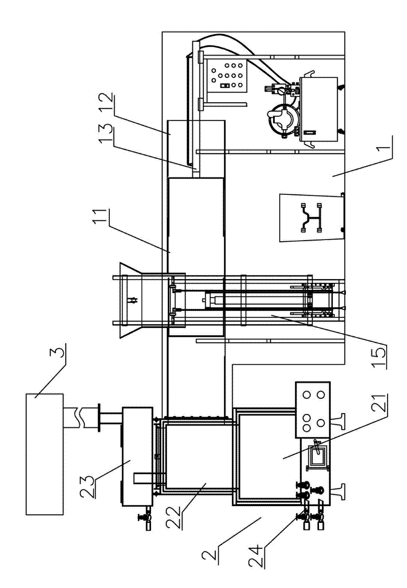
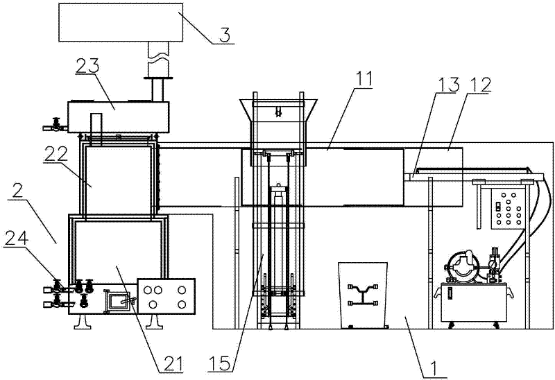
[0015] refer to figure 1 , an automatic feeding heat energy garbage disposer, comprising a feeding unit 1, a thermal energy decomposition unit 2 and an exhaust gas treatment unit 3 connected in sequence, the feeding unit 1 comprising at least one delivery pipeline 12 with a feed inlet 11, the delivery pipeline One end of 12 is connected with the thermal energy decomposition unit 2, and the other end is provided with a piston push rod 13.

[0016] As a further preferred embodiment, the feed inlet 11 is located in the middle of the conveying pipeline 12, and a material lifting frame 15 is arranged beside it. Specifically, the material lifting frame 15 has a hook, and the trash can can be hooked on the frame, and then driven by a motor, the material lifting frame 15 can automatically lift the trash can to the feed port 11 to dump garbage.

[0017] As a further preferred embodiment, the feeding unit 1 further includes a hydraulic power system coupled with the piston push rod 13 ,...


PUM


Abstract

The invention discloses an automatic feeding heat energy garbage treatment machine, which comprises a feeding unit, a heat energy decomposition unit and a tail gas treatment unit connected sequentially, wherein the feeding unit comprises at least one delivery duct provided with a feeding hole, one end of the delivery duct is connected with the heat energy decomposition unit, and a piston push rod is arranged at the other end of the delivery duct. Through the delivery duct and the piston push rod, after the garbage to be treated is poured into the delivery duct from the feeding hole, the garbage can be pushed to the heat energy decomposition unit through the piston push rod and subjected to heat energy decomposition, so that the problems of slow feeding and low efficiency in heat energy garbage treatment are effectively solved. The automatic feeding heat energy garbage treatment machine is simple and reliable in structure, and can be widely applied to the occasions of garbage treatment.

Description

technical field [0001] The invention relates to a garbage disposal device, in particular to a heat energy garbage disposal machine. Background technique [0002] Thermal energy garbage disposer is a new type of machine that uses thermal energy to decompose garbage. It usually has three parts: feeding unit, thermal energy decomposition unit and exhaust gas treatment unit. The thermal energy decomposition unit is a single-layer combustion chamber, equipped with an energy conversion device used in conventional thermal energy waste disposal machines; the feeding unit is actually a feeding port, connected with the combustion chamber, and the garbage can be directly dumped into the combustion chamber by mechanical or manual means The exhaust gas treatment unit is a conventional air purification system such as a water bath device and an electronic dust removal device, which is connected to the upper end of the combustion chamber. The waste gas generated after the garbage is decompo...

Claims


Application Information

Patent Timeline
Patent Type & Authority Applications(China)
IPC IPC(8): B09B3/00
Inventor 陈树华
Owner 陈树华
Learn More