
PUCCH resource mapping method and apparatus thereof

A technology for resource mapping and resource configuration information, which is applied to digital transmission systems, electrical components, and error prevention to achieve the effects of reducing the number of PUCCH resources, flexibly configuring PUCCH resources, and improving uplink transmission efficiency

Active Publication Date: 2012-02-15
DATANG MOBILE COMM EQUIP CO LTD
View PDF3 Cites 70 Cited by
  • Summary
  • Abstract
  • Description
  • Claims
  • Application Information

AI Technical Summary

Problems solved by technology

[0027] However, the disclosed technologies in the prior art only provide related processing solutions for traditional PDCCH resource->PUCCH resource mapping, and do not provide specific processing solutions for enhanced PDCCH->PUCCH resource mapping

Method used


Image

  • PUCCH resource mapping method and apparatus thereof
  • PUCCH resource mapping method and apparatus thereof
  • PUCCH resource mapping method and apparatus thereof

Examples


Embodiment b

[0095] Embodiment b: In the LTE TDD system, M≥1, the UE needs to perform UCI feedback on the PDCCH received in M ​​downlink subframes in the same uplink subframe, as shown in Table 1; in this case Next, when step 620 is executed, the UE needs to determine a PUCCH resource in each of the M subframes for the N E-PDCCH clusters configured by the system according to the preset resource configuration information, that is, any E-PDCCH cluster - The PDCCH cluster corresponds to one PUCCH resource in each of the M subframes.

[0096] For example, assume that N E-PDCCH clusters are configured in the system, and their numbers are E-PDCCH-1, E-PDCCH-2, ..., E-PDCCH-N. At the same time, assuming any E-PDCCH cluster, Denoted as E-PDCCH-n (1≤n≤N), the numbers of the corresponding PUCCH resources in each of the M subframes are PUCCH-n-1, PUCCH-n-2,... , PUCCH-n-M, wherein, PUCCH-n-m (1≤n≤N, 1≤m≤M) indicates the PUCCH resource corresponding to the PDCCH transmitted by E-PDCCH-n in the mth su...

Embodiment c

[0124] Embodiment c, in the LTE FDD system, M=1, if the UE is configured to detect PDCCHs corresponding to K downlink component carriers on one carrier, then the UE receives at most K PDCCHs in one E-PDCCHcluster in one downlink carrier If the PDCCH that needs to feed back UCI, the UE needs to perform UCI feedback on the PDCCH received in an E-PDCCH cluster in one uplink subframe. In this case, when performing step 620, the UE needs to use the preset resource The configuration information determines corresponding K PUCCH resources for each E-PDCCH cluster, that is, K PUCCH resources corresponding to any E-PDCCH cluster.

[0125] For example, assume that N E-PDCCH clusters are configured in the system, and their numbers are E-PDCCH-1, E-PDCCH-2, ..., E-PDCCH-N. At the same time, assuming any E-PDCCH cluster, Denoted as E-PDCCH-n (1≤n≤N), the numbers of the PUCCH resources corresponding to each of the K component carriers are PUCCH-n-1, PUCCH-n-2,... , PUCCH-n-K, where PUCCH-n-...


PUM


Abstract

The invention relates to the communication field, and discloses a PUCCH (physical uplink control channel) resource mapping method and an apparatus thereof used for effectively reducing a quantity of reserved PUCCH resources in a system. The method comprises the following steps: setting resource configuration information which is used for indicating a PUCCH resource which is corresponding to each E-PDCCH cluster which is configured by the system, according to the resource configuration information, UE and a base station respectively determine at least one E-PDCCH resource corresponding to each E-PDCCH cluster which is configured by the system, and transmit UCI on an E-PDCCH resource which exists PDCCH transmission and is corresponding to the E-PDCCH cluster. In this way, flexible PUCCH resource configuration can be provided for an Enhanced PDCCH, simultaneously the quantity of the reserved PUCCH resources in the system can be effectively reduced, and an uplink resource utilization rate is raised.

Description

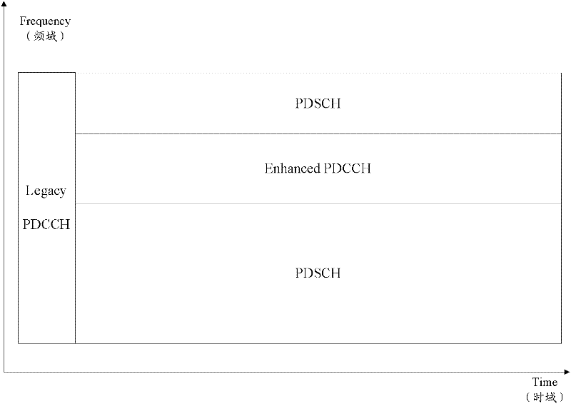
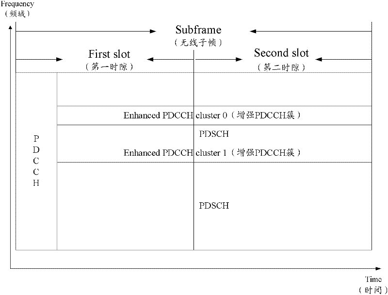
technical field [0001] The present invention relates to the communication field, in particular to a method and device for PUCCH resource mapping. Background technique [0002] In the LTE (Long Term Evolution) system, the PDCCH (Physical Downlink Control Channel) is sent in each radio subframe, and forms a TDM (Time Division Multiplexing) relationship with the PDSCH (Physical Downlink Shared Channel) that transmits downlink data. refer to figure 1 As shown, the PDCCH is transmitted through the first N OFDM (Orthogonal Frequency Division Multiplexing, Orthogonal Frequency Division Multiplexing) symbols of a downlink subframe, wherein, the possible values ​​of N are 1, 2, 3, 4, and N=4 It is only allowed to appear in systems with a system bandwidth of 1.4MHz. [0003] With the continuous evolution of the LTE-Advanced (Long Term Evolution) standard, as well as COMP (Coordinated Multiple Point, coordinated multi-point) transmission, enhanced MU-MIMO (Muti-User-MIMO, multi-user ...

Claims


Application Information

Patent Timeline
Patent Type & Authority Applications(China)
IPC IPC(8): H04L1/00H04W72/04H04W72/12
CPCH04W72/21
Inventor 沈祖康林亚男赵锐
Owner DATANG MOBILE COMM EQUIP CO LTD
Learn More