Stator rib for motors

A stator rib and stator technology is applied in the manufacture of motor generators, electrical components, electromechanical devices, etc., and can solve the problems of difficult processing and reduced efficiency.

Inactive Publication Date: 2012-02-15
SHANDONG HUALI ELECTRIC MOTOR GRP
View PDF0 Cites 0 Cited by
  • Summary
  • Abstract
  • Description
  • Claims
  • Application Information

AI Technical Summary

Problems solved by technology

[0004] The purpose of the present invention is to provide a stator bar to overcome the technical problems of difficult processing and reduced efficiency caused by the current use of bar steel as the stator bar

Method used


Image

  • Stator rib for motors
  • Stator rib for motors

Examples


Embodiment Construction

[0009] The present invention will be further described below in conjunction with the accompanying drawings and embodiments.

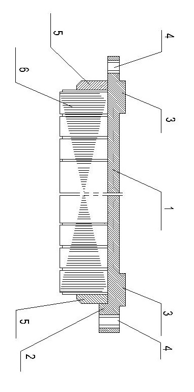
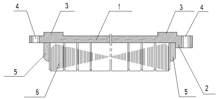
[0010] As shown in the attached picture, after 7 stacks of stator punching sheets are integrated into the motor stator, the stator ribs are evenly welded on the surface of the outer circle of the motor stator. Generally, 6 or 8 stator ribs are welded on the outer circle of the stator. Together with a sectional view of the stator.

[0011] As shown in the accompanying drawings, the stator bar includes a square bar steel 1, a stator ring holder 2 is processed on the back of one end of the square bar steel, and two ring rib plate clamps 3 are processed on the front of the square bar steel. Both ends of the bar steel are processed with threaded holes 4 for installing the motor windshield.

[0012] When processing the stator ribs, the length of the bar steel 1 is determined according to the specifications of the motor stator, and the distance between the ri...


PUM


Abstract

The invention belongs to the technical field of motor processing production. For solving the technical problems of processing difficulty and efficiency reduction caused by taking steel bars as stator ribs currently, the invention adopts a technical scheme as follows: a stator rib for motors comprises a quadrate steel bar; and the stator rib for motors is characterized in that a stator pressing-ring clamped platform is processed on the back of one end of the quadrate steel bar, two looped rib plate clamped platforms are processed on the front face of the quadrate steel bar, and screwed holes for installing a motor wind deflector are processed at the two ends of the quadrate steel bar. When the stator rib is welded to a stator core, the positioning is accurate, the subsequent processing is simple, and the efficiency is high; and when the stator core and a motor base are assembled, the positioning is easy, and a position relation between the stator core and the motor base can be guaranteed.

Description

[0001] technical field [0002] The invention belongs to the technical field of motor processing and production, and specifically refers to a stator bar for a motor. Background technique [0003] Stator ribs are welded on the stator core of the high-voltage motor, and the stator punches are welded into one body by the stator ribs and the stator pressure ring. Usually, the stator rib blank is made of unprocessed square bar steel, which is directly welded with the stator punching sheet and the stator pressure ring. Since the stator rib has no positioning restrictions during welding and assembly with the machine base, it brings a large amount of processing to subsequent production, and the processing is relatively large. Difficulties, resulting in reduced production efficiency. Contents of the invention [0004] The purpose of the present invention is to provide a stator bar to overcome the technical problems of processing difficulty and efficiency reduction caused by the cu...

Claims


Application Information

Patent Timeline
IPC IPC(8): H02K15/00
Inventor 孙晓霞林治新马志强
Owner SHANDONG HUALI ELECTRIC MOTOR GRP
Why Eureka
Try Eureka