
Reactive-power control method of wind power field

A technology for power control and wind farms, applied in reactive power adjustment/elimination/compensation, wind power generation, reactive power compensation, etc. It can solve the problems of not establishing coordination relationship, wind turbine off-grid, and high system voltage, so as to avoid system problems. Effects of overvoltage, reduced burden, and low economical cost

Active Publication Date: 2012-02-15
NORTH CHINA ELECTRIC POWER UNIV (BAODING) +1
View PDF5 Cites 44 Cited by
  • Summary
  • Abstract
  • Description
  • Claims
  • Application Information

AI Technical Summary

Problems solved by technology

However, in wind farms built in multiple phases, multiple SVCs and SVGs often coexist. Due to the lack of coordination of multiple reactive power compensation devices, voltage oscillations are prone to occur during adjustment.
Moreover, the dynamic reactive power compensation equipment generates a large amount of reactive power during the low-voltage ride-through process caused by system faults, resulting in excessive system voltage after the fault is eliminated, and the wind turbine is disconnected from the grid due to the system over-voltage protection action.
[0005] In addition, the reactive power control and active power control in the existing wind farms are independent, and there is no coordination relationship between them

Method used


Image

  • Reactive-power control method of wind power field
  • Reactive-power control method of wind power field
  • Reactive-power control method of wind power field

Examples


Embodiment Construction

[0027] The specific embodiments of the present invention will be described in further detail below in conjunction with the accompanying drawings:

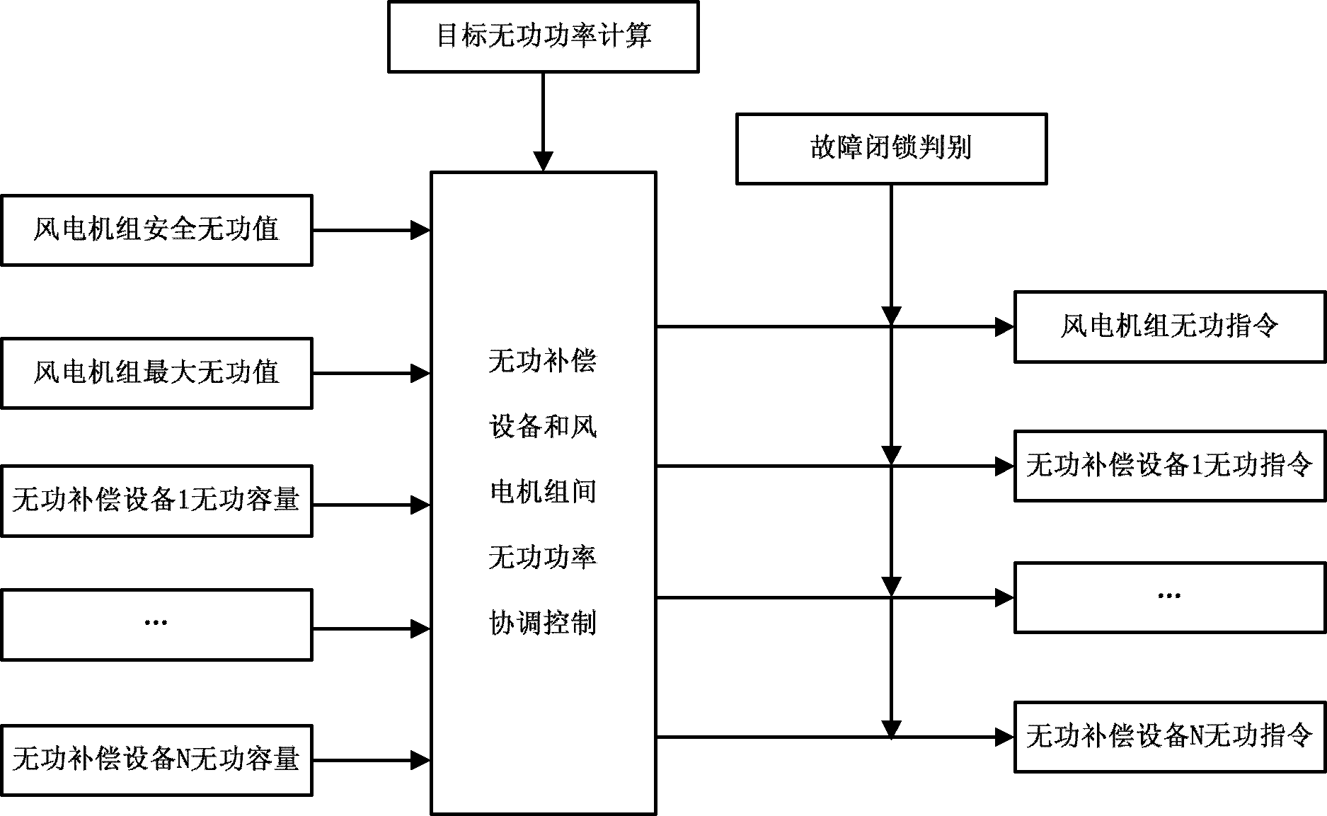
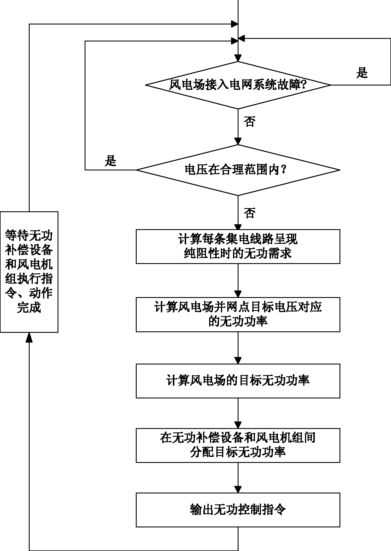
[0028] The control method of the invention takes the voltage of the grid-connected point of the wind farm as the control target. When the system is disturbed or the voltage fluctuation is caused by the wind speed and load changes of the wind farm, the voltage of the grid-connected point is adjusted by the coordinated control of the reactive power compensation equipment and the wind turbine. Track voltage target value. like figure 1 Shown is the data flow diagram in the reactive power control method of the wind farm of the present invention. The reactive power coordinated control between the reactive power compensation equipment and the wind turbine depends on the effective reactive power capacity of the reactive power compensation equipment and the wind turbine and the wind power. The relationship between the target reactive power...


PUM


Abstract

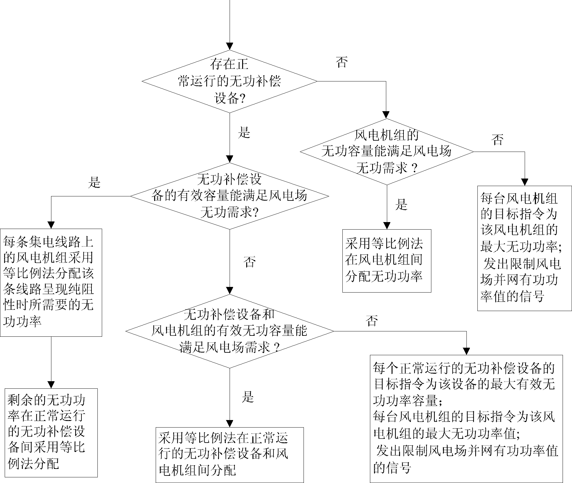
The invention discloses a reactive-power control method of a wind power field, which is suitable for performing reactive-power coordinated control on a wind power field variable-speed constant-frequency wind power generating set and a reactive-power compensation device. The control method comprises the steps that: reactive-power requirements of the wind power field are calculated, and a correspondent allocation method is adopted according to the valid reactive-power power capacities of the reactive-power compensation device and the wind power generating set. Due to the adoption of the controlmethod, the reactive-power power adjusting capacity of the variable-speed constant-frequency wind power generating set can be adequately played, the coordinated control of multiple reactive power sources can be realized, and the oscillation situation caused by the adjustment can be avoided. When an electric power system has malfunctions, the reactive power adjustment is locked, so the system over-voltage caused by the excessive reactive power of the system after the malfunction is removed can be prevented. When the reactive power capacity of the wind power field is insufficient to maintain the voltage of an interconnected point, a prompting signal is transmitted, the active power of the wind power field is limited, and the coordination of the active power and the reactive power can be realized.

Description

technical field [0001] The invention relates to a reactive power control method for a wind farm, and belongs to the technical field of power generation in a power system. Background technique [0002] In recent years, wind power, as one of the most promising new energy technologies for large-scale development and commercialization, has developed rapidly at an unprecedented speed. The connection of wind power generation to the power grid brings many problems to the power system, among which the problem of voltage and reactive power is one of the most prominent problems. [0003] With the continuous development of wind turbine technology, variable-speed constant-frequency wind turbines have gradually become the mainstream models of wind farms, mainly including doubly-fed asynchronous wind turbines and direct-drive permanent magnet synchronous wind turbines. The variable speed constant frequency wind power technology realizes the decoupling control of active power and reactive...

Claims


Application Information

Patent Timeline
Patent Type & Authority Applications(China)
IPC IPC(8): H02J3/18H02J3/38
CPCY02E10/76Y02E40/30
Inventor 连倩崔彦波王晓峰奚志江苏亚楠刘静芳
Owner NORTH CHINA ELECTRIC POWER UNIV (BAODING)
Learn More