Rapid high precision frequency measuring realization method by applying FPGA chip

A frequency measurement, high-precision technology, applied in the field of fast and high-precision frequency measurement, can solve problems such as large errors, and achieve the effect of speeding up processing speed, improving real-time performance, and improving frequency measurement accuracy

Inactive Publication Date: 2012-02-15
NANJING UNIV OF AERONAUTICS & ASTRONAUTICS
View PDF2 Cites 7 Cited by
  • Summary
  • Abstract
  • Description
  • Claims
  • Application Information

AI Technical Summary

Problems solved by technology

The frequency measurement error of the Rife method in the central area of ​​the quantization frequency is very small, close to CLRB, but the error near the FFT quantization frequency is relatively large

Method used


Image

  • Rapid high precision frequency measuring realization method by applying FPGA chip
  • Rapid high precision frequency measuring realization method by applying FPGA chip
  • Rapid high precision frequency measuring realization method by applying FPGA chip

Examples


Embodiment Construction

[0042] Below in conjunction with accompanying drawing, the technical scheme of invention is described in detail:

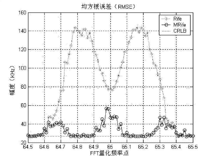
[0043] This method is improved on the basis of the Rife method, and is now named the MRife method (modified Rife method).

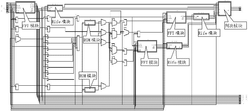
[0044] Such as figure 1 As shown, add three FFT modules, three Rife modules, and two ROM modules on the FPGA chip. The FFT module completes the FFT operation, the Rife module completes the Rife algorithm, and the ROM module is used to store the real part and imaginary part of the complex exponent required for translation of the input signal.

[0045] Such as Figure 8 Shown: a method for fast and high-precision frequency measurement implemented by an FPGA chip, comprising the following steps:

[0046] A method for fast and high-precision frequency measurement implemented by an FPGA chip, comprising the steps of:

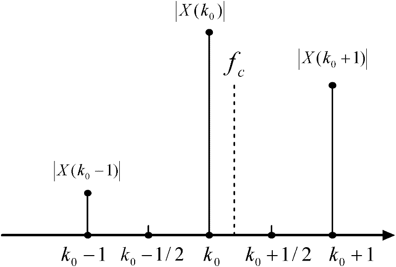
[0047] Step 1. Divide the input signal into three parallel channels. The first input signal is shifted by -1 / 3FFT quantization...


PUM


Abstract

The invention relates to a rapid high precision frequency measuring realization method by applying an FPGA chip, belonging to the digital signal processing field. According to the method, an FFT module, a Fife module and an ROM module are added into the FPGA chip, an input signal is divided into three signals, wherein, two signals are subjected to frequency shift, the other signal is not subjected to frequency shift, on a basis of Rife, a real part absolute value and an imaginary part absolute value of an FFT operation result are compared to determine a frequency spectrum maximum value, threefrequency measuring results are obtained respectively, and a maximum value is selected as a final frequency measured value. According to the method, frequency measuring precision of a fixed-length receiving signal is raised, a processing speed is accelerated, and a real-time property of a system is raised.

Description

technical field [0001] The invention relates to a fast and high-precision frequency measurement method realized by using an FPGA chip, belonging to the field of digital signal processing. Background technique [0002] Frequency measurement is an important problem in engineering fields such as electronic reconnaissance, radar, and communication. Under different signal-to-noise ratio conditions, the frequency measurement accuracy obtained by different methods is different, but no matter which frequency measurement method is used, the root mean square error (RMSE) of the frequency measurement will not be less than a lower limit: carat Mei-Rao Boundary [3] (CLRB). The maximum likelihood frequency measurement method (ML) given in [3] can reach this limit, so it is called the optimal measurement. However, the ML method needs to perform one-dimensional search, which requires a large amount of calculation and poor real-time processing performance, which is not convenient for engin...

Claims


Application Information

Patent Timeline
Patent Type & Authority Applications(China)
IPC IPC(8): G01R23/16
Inventor 王旭东
Owner NANJING UNIV OF AERONAUTICS & ASTRONAUTICS
Why Eureka
Try Eureka