Power transmission apparatus using a planetary gear

A technology of power transmission device and planetary gear carrier, applied in the direction of gear transmission device, power device, transmission device, etc., can solve the problems of torque loss, difficulty in shifting, etc.

Inactive Publication Date: 2012-02-08
河太焕
View PDF0 Cites 1 Cited by
  • Summary
  • Abstract
  • Description
  • Claims
  • Application Information

AI Technical Summary

Problems solved by technology

[0006] However, according to the above method, the torque of the driving power source will act on the variable speed power source, which results in severe torque loss
In addition, the rotational speed of the driving power source will be directly input to the planetary gear set without deceleration, which causes a problem that if the shifting power source does not provide strong torque, shifting is difficult

Method used


Image

  • Power transmission apparatus using a planetary gear
  • Power transmission apparatus using a planetary gear
  • Power transmission apparatus using a planetary gear

Examples


Embodiment Construction

[0115]The nature and mode of operation of the invention will be more fully described in the following detailed description of the invention, taken in conjunction with the accompanying drawings.

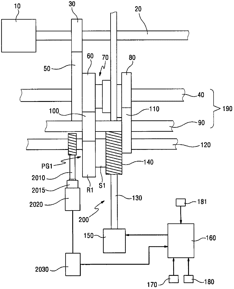
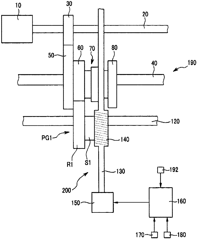
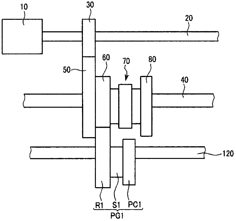
[0116] figure 1 is a representative schematic diagram illustrating the configuration of the power transmission device according to the first embodiment of the present invention, figure 2 is description figure 1 A representative schematic diagram of the construction of the power transmission omitting the idler shaft, and image 3 is description figure 2 A representative schematic diagram of the construction of the power transmission omitting the transmission input shaft.

[0117] like Figure 1 to Figure 3 As shown, the power transmission device according to the first embodiment of the present invention includes an input shaft 20 , a reduction unit 190 , a planetary gear set PG1 , an output shaft 120 , a transmission unit 200 and a control unit 160 .

[0118] The input shaft 20 ...


PUM


Abstract

The present invention relates to a planetary gear set with one side of a planetary carrier extending to form gear teeth, and to a power transmission apparatus having reduced rotating speed input from a driving power source and input to one actuating means of the planetary gear set and a transmission power source rotating speed is input to the other actuating means to achieve a plurality of gear shifts, and which receives generating power from an output shaft, stores electrical energy, and utilizes the stored electrical energy to control transmission power source, thereby controlling the transmission input shaft with ease. The power transmission apparatus comprises: an input shaft, one end of which is constantly connected to the driving power source to receive power, and to which a driving gear is fixed; a deceleration unit coupled to the driving gear to reduce the rotating speed of the input shaft; a planetary gear set including 1st actuating means coupled to the deceleration unit to receive rotating speed of the deceleration unit, 2nd actuating means for receiving gear-shifting power, and 3rd actuating means for generating output speed; a gear shift unit connected to the transmission power source to receive power for gear-shifting, and coupled to the 2nd actuating means to transmit power for gear-shifting to the 2nd actuating means; and an output shaft fixed at the 3rd actuating means to deliver an output speed. The 2nd actuating means has a rotary shaft and the gear shaft unit has a rotary shaft, wherein the two rotary shafts are arranged vertically to one another. A torque control shaft is connected to the 2nd actuating means to receive rotating force of the 2nd actuating means via power transmission means. The torque control shaft is equipped with a generator for generating electrical energy. A battery for supplying power to the transmission power source is connected to the generator.

Description

technical field [0001] The present invention generally relates to a power transmission using planetary gears, which can be used in motor vehicles, ships, windmills and alternator motors, etc., and more particularly, the present invention relates to a power transmission including a planetary The gear set has a planetary gear carrier, one side of which is extended to form gear teeth, wherein the rotational speed input from the driving power source is reduced and then input to one running member of the planetary gear set, and the rotational speed of the variable speed power source is Input to another running member of the planetary gear set to achieve multi-stage gears, and obtain the power for generating electricity from the output shaft, the generated electricity is stored, and the stored electric energy is used as the control energy source of the variable speed power source so that it is easy control the drive input shaft. Background technique [0002] In general, a transmi...

Claims


Application Information

Patent Timeline
Patent Type & Authority Applications(China)
IPC IPC(8): F16H3/44F16H59/14F16H59/02
CPCB60K6/48F16H3/72Y02T10/62Y02T10/72F16H3/721F16H37/046F16H59/14F16H63/062
Inventor 河太焕
Owner 河太焕
Why Eureka
Try Eureka