
Control method and control system for large-scale photoelectric telescope lens mechanism distribution

A technology of photoelectric telescope and control method, applied in the direction of electrical program control, comprehensive factory control, comprehensive factory control, etc., can solve problems such as not being suitable for the development trend of photoelectric telescope, increasing equipment unreliability, complex wiring and integration, etc. Achieve the effects of favorable debugging and maintenance, easy expansion and tailoring, and simplified operation

Inactive Publication Date: 2014-03-05
INST OF OPTICS & ELECTRONICS - CHINESE ACAD OF SCI
View PDF7 Cites 0 Cited by
  • Summary
  • Abstract
  • Description
  • Claims
  • Application Information

AI Technical Summary

Problems solved by technology

[0003] The first method requires the external controller to have multiple output ports to support point-to-point connections. There are many intermediate connection lines. When used on a photoelectric telescope, the wiring and integration are complicated, which increases the unreliability of the equipment and is relatively complicated in program design. Currently less used
The problem with the second method is that if a node in the middle fails, it will cause this node and all subsequent nodes to be out of control, setting the entire network to be occupied by wrong data and lead to paralysis, and the later the node in the application, the greater the communication delay , not very suitable for the development trend of real-time control of photoelectric telescopes
The third method is suitable for application on photoelectric telescopes, represented by the RS485 bus. The problem is that the half-duplex single-master mode requires only one node to send data at a time.

Method used

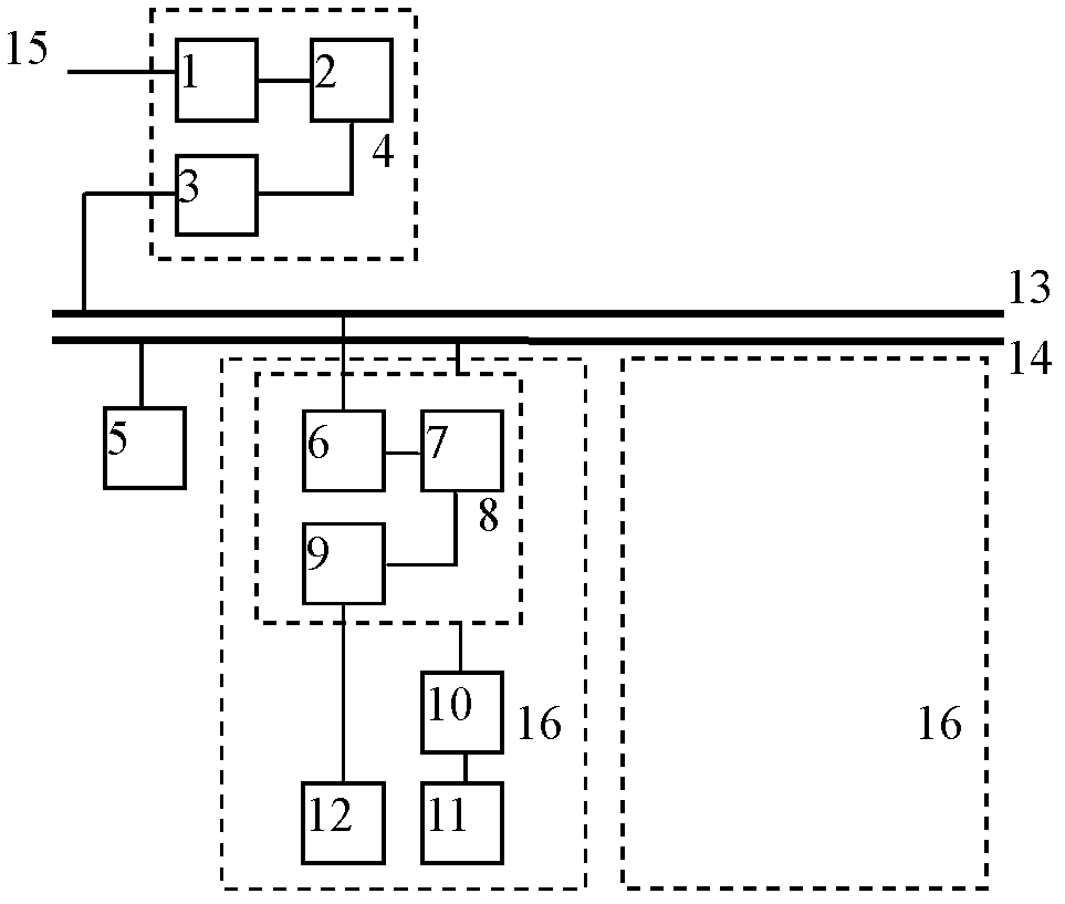
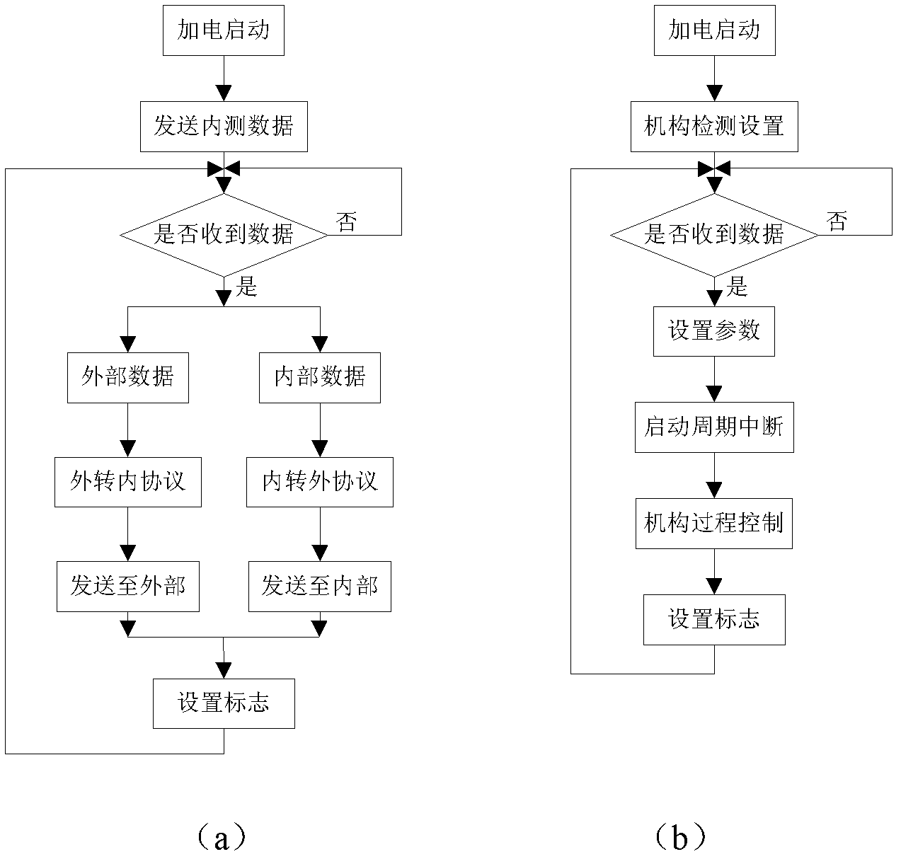
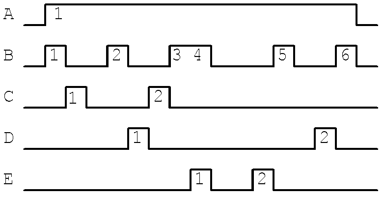

Image

  • Control method and control system for large-scale photoelectric telescope lens mechanism distribution
  • Control method and control system for large-scale photoelectric telescope lens mechanism distribution
  • Control method and control system for large-scale photoelectric telescope lens mechanism distribution

Examples


Embodiment

[0035] The 1.2m photoelectric telescope uses the CAN bus to control the various mechanisms of the detector lens, including several main lenses such as rough tracking, capture, high sensitivity, secondary mirror, and third mirror. The control mechanisms include camera power supply, coarse tracking lens filter, etc. Light sheet, coarse tracking lens magnification, capture lens filter, high-sensitivity lens aperture, high-sensitivity lens focus, secondary mirror focus and encoder, third mirror x, y, z three-axis and three-axis encoder, Instrument temperature, etc., interface nodes and control node boards are developed by TMS320LF2407A, externally connected by RS422, baud rate 115200bps, internal CAN bus connection, 29-bit extended ID, rate 1Mbps. The external serial data format of 8*8bits and the internal data format of CAN bus of 4*16bits are designed. During the debugging process, plug and play when the hardware connection and software protocol interface are satisfied, disconne...


PUM


Abstract

The invention discloses a control method for the large-scale photoelectric telescope lens mechanism distribution, which aims at solving some problems in the existing method. A universal standard bus protocol is introduced into the specific application of the large photoelectric telescope lens, and a method for realizing the real-time reliable control through connecting a plurality of mechanisms in parallel into a control network. The control network is adopted to be connected with the outside through an interface node, and the interface node and each control node are connected inside the control network in a bus mode. On the data protocol structure, the external interface data format and the control network inside the data format are designed, the uniqueness of each node code is ensured through the sectional design of the node identity (ID), the concrete operation object code corresponds to a photoelectric telescope mechanism name, and the understanding and the application are convenient. The method has the advantages that the structure is simple and compact, the module is independent, the universality is high, the transplanting is flexible, and the method is applicable to the control of each mechanism of lens in scattered installation on the photoelectric telescope.

Description

technical field [0001] The present invention relates to a distributed control method and a control system, in particular, a distributed control method and a control system for each lens mechanism of a large-scale photoelectric telescope, which is applicable to a part or the entire photoelectric telescope lens mechanism, and can also be used for the photoelectric telescope Controls by other relevant agencies are included. Background technique [0002] At present, with the development of technology and the deepening of research, the functions of large-scale photoelectric telescopes have been continuously enhanced, and various photoelectric lenses and related equipment loaded on the rack have also increased. These devices are scattered and fixedly installed on the rack, making system connection and control difficult. and complexity increases. There are generally three existing control methods, the first is point-to-point connection, each lens is equipped with a controller, and...

Claims


Application Information

Patent Timeline
Patent Type & Authority Patents(China)
IPC IPC(8): G05B19/418
CPCY02P90/02
Inventor 王岱吴钦章
Owner INST OF OPTICS & ELECTRONICS - CHINESE ACAD OF SCI
Learn More