
Anchor device and communication box

A communication box and adapter technology, which is applied in the direction of optical waveguide coupling, fiber mechanical structure, etc., can solve the problems of communication box occupying a large space, complex structure, insufficient parking modules, etc., and achieve the effect of convenient operation and simple structure

Active Publication Date: 2015-04-29
SUS TELECOMM
View PDF3 Cites 0 Cited by
  • Summary
  • Abstract
  • Description
  • Claims
  • Application Information

AI Technical Summary

Problems solved by technology

[0005] The purpose of the embodiment of the present invention is to provide a mooring device, aiming to solve the problem that the existing communication box needs to be equipped with a mooring area and the mooring modules in the mooring area are not enough
[0007] Another object of the embodiments of the present invention is to provide a communication box, which aims to solve the problems of large space occupation, complex structure and complicated operation of existing communication boxes

Method used


Image

  • Anchor device and communication box
  • Anchor device and communication box
  • Anchor device and communication box

Examples


Embodiment 1

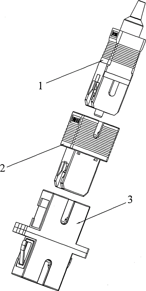
[0028] Such as Figure 1~4 As shown, the mooring device 2 is used to connect the optical fiber plug 1 and the adapter 3, and the optical fiber plug 1 and the adapter 3 are respectively placed at the two ends of the mooring device 2, and are also respectively connected to the two ends of the mooring device 2. At the same time, when the three are connected in Together, the mooring device 2 also plays the role of fixing the optical fiber plug 1 and blocking dust. There is a partition 21 inside the docking device 2, and the partitioning layer 21 can cut off the communication between the two ends of the docking device, so the optical fiber plug 1 and the adapter 3 are connected behind the docking device without any connection between them. Simultaneously, the interlayer 21 is integrated with the mooring device 2, does not need additional design and installation, and can be processed and formed with the mooring device 2 at one time.

[0029] The shape of the above-mentioned mooring...

Embodiment 2

[0037] Such as Figure 5-8 As shown, the mooring device 2 is used to connect the optical fiber plug 1 and the adapter 3, and the optical fiber plug 1 and the adapter 3 are respectively placed at the two ends of the mooring device 2, and are also respectively connected to the two ends of the mooring device 2. At the same time, when the three are connected in Together, the mooring device 2 also plays the role of fixing the optical fiber plug 1 and preventing dust. The interior of the mooring device 2 is provided with an interlayer 21, which can isolate the coupling connection at both ends of the mooring device, so the optical fiber plug 1 and the adapter 3 are connected behind the mooring device without any connection between them. Simultaneously, the interlayer 21 is integrated with the mooring device 2, does not need additional design and installation, and can be processed and formed with the mooring device 2 at one time.

[0038] The shape of the above-mentioned mooring devi...


PUM


Abstract

The invention belongs to the optical fiber communication technology field and provides an anchor device. The anchor device is used to connect an optical fiber plug and an adapter. One end of the anchor device forms cooperation connection with the optical fiber plug and the other end forms the cooperation connection with the adapter. An interlayer which is used to block the connection of the two ends is arranged in the anchor device. The invention also provides a communication box which comprises: a box body, the adapter arranged in the box body and the anchor device. In the invention, the two ends of the anchor device are respectively directly connected with the optical fiber plug and the adapter so that effects of dust resistance and optical fiber plug fixation can be achieved; the interlayer is arranged in the anchor device so that the connection of the optical fiber plug and the adapter on the two ends is blocked. A structure is simple and operation is very convenient. The communication box provided in the invention comprises the anchor device so as to avoid arranging an anchor area in the box. Therefore, a volume is small. The structure is simple and compact. The communication box has many other characteristics.

Description

technical field [0001] The invention belongs to the field of optical fiber communication, in particular to a mooring device and a communication box. Background technique [0002] In the prior art, there are the following two methods for connecting two optical fibers together. One, the permanent fixed connection of the two optical fibers; Remove the connected adapter) for an active connection. [0003] However, in practical applications, there are often not all lines in the communication box (such as optical fiber connection box, optical cable transfer box, etc.) connected to the user at once, so it is necessary to connect some optical fiber lines in the communication box at this time. Cut off, so that the fiber optic plug is not connected to the adapter, the common method is to use the above method two, insert the fiber optic plug into the adapter, so that the line is connected, but if you want to disconnect the line, you can only leave a certain space in the box as a parki...

Claims


Application Information

Patent Timeline
Patent Type & Authority Patents(China)
IPC IPC(8): G02B6/38G02B6/44
Inventor 刘灿胜邵海波杨赞
Owner SUS TELECOMM
Learn More