


Quick Research
Generate reliable direction feasibility study reports for your R&D in just a few steps.

Technical Q&A
Discover and master advanced knowledge NOW. Basics, ideas, possibilities, all at once.

Find Solutions
As an expert in R&D theories, this can generate solutions to your technical problems instantly.

Evaluate Feasibility
Analyze your overall solution with one click, know your potential R&D risks in advance.

Monitor Landscape
Get weekly tech updates, stay abreast of the latest tech innovations and key insights.
Electric energy meter for PFTTX (power fiber-to-the-x, x = H for home, P for premises, C for curb and N for node or neighborhood) and wiring method
A technology of electric energy meter and power supply line, which is applied in the field of combining electric energy metering and network communication, can solve problems such as uneconomical, aesthetically pleasing, and troublesome, and achieve the effects of cost saving, simple structure, and convenient use
- Summary
- Abstract
- Description
- Claims
- Application Information
AI Technical Summary
Problems solved by technology
Method used
Image

Examples
Embodiment 1
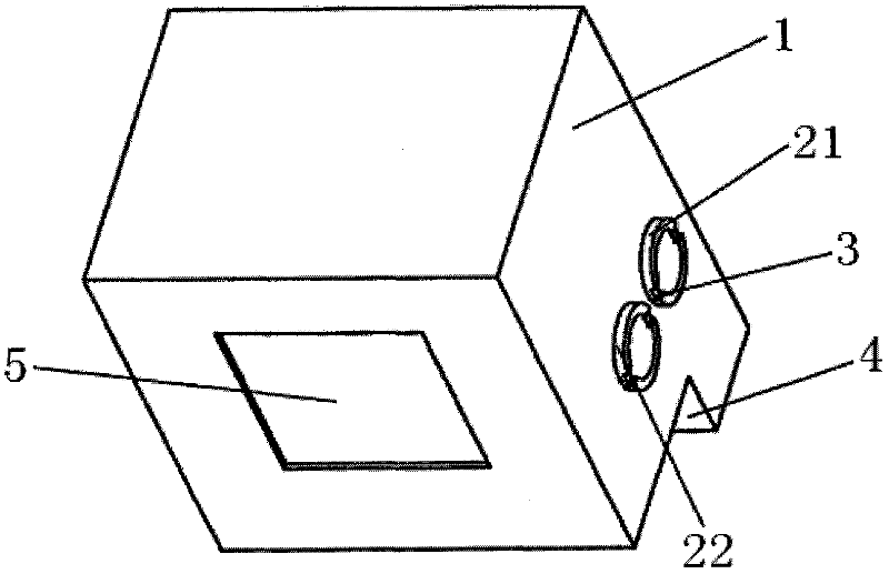
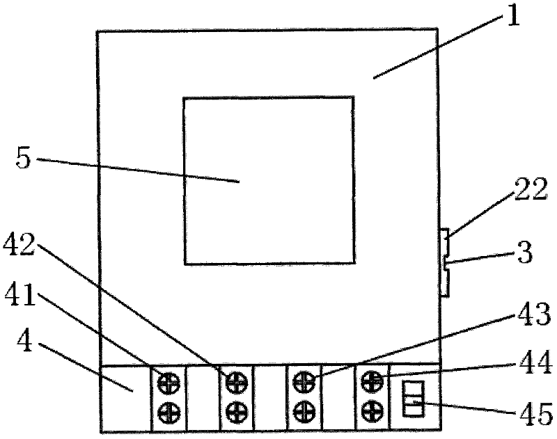
[0047] please see figure 1 and figure 2 , a PFTTX electric energy meter, which includes a measuring mechanism, a housing 1, a display unit 5, a wiring unit 4, the wiring unit has a plurality of terminals; the measuring mechanism is located in the housing; it is characterized in that the housing There is an optical fiber input interface 21 and an optical fiber output interface 22 on the right side; there is also an optical signal transceiver device in the housing; the optical fiber input interface is connected to the input end of the optical signal transceiver device, and the optical fiber output interface is connected to the optical signal transceiver device. Output end; the optical fiber input interface can be connected with an external optical fiber, and the optical fiber output interface can be connected with an external optical fiber; both the optical fiber input interface and the optical fiber output interface have slots 3 for fixing, and the outside has threads; the wir...
Embodiment 2
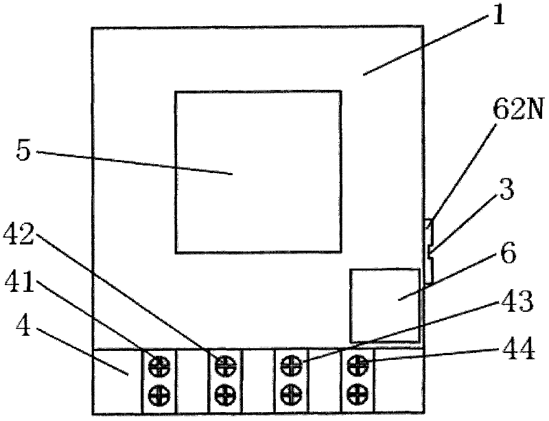
[0049] please see image 3 and Figure 4 , and combined with figure 1 , a PFTTX electric energy meter, which includes a measuring mechanism, a housing 1, a display unit 5, a wiring unit 4, the wiring unit has a plurality of terminals; the measuring mechanism is located in the housing; it is characterized in that the housing There is an optical fiber input interface 61 and multiple optical fiber output interfaces on the right side; the multiple optical fiber output interfaces are 621, 622, etc. until 62N-1, 62N; of course, N is greater than or equal to 2; there is also a planar waveguide optical fiber in the housing. Splitter 6; the optical fiber input interface is connected to the input end of the planar waveguide optical splitter, and the optical fiber output interface is connected to the output end of the planar waveguide optical splitter; the optical fiber input interface can be connected to an external optical fiber, and the optical fiber output interface can be connected...
Embodiment 3
[0056] please see Figure 5 and Figure 7 , power supply line 7 is made of optical fiber 73, phase line 71, zero line 72, and the sheath 74 that covers them; A kind of wiring method of PFTTX electric energy meter is characterized in that it comprises the following steps:
[0057] The first step: stripping one end of the first power supply line 7 with the optical fiber;
[0058] Second step: connect the phase line 71 and the neutral line 72 of one end of the stripped first power supply line to the input terminals 41 and 43 of the electric energy meter respectively; connect the optical fiber 73 to the connector, and then connect it to the The input terminal 21 of the optical signal transceiving device;
[0059] Step 3: Strip one end of the second power supply line with optical fiber;
[0060] Step 4: Connect the phase line 71 and neutral line 72 of one end of the stripped second power supply line to the output terminals 42 and 44 of the electric energy meter respectively; con...
PUM
 Abstract
Description
Claims
Application Information
 - R&D Engineer
- R&D Manager
- IP Professional
- Industry Leading Data Capabilities
- Powerful AI technology
- Patent DNA Extraction
Browse by: Latest US Patents, China's latest patents, Technical Efficacy Thesaurus, Application Domain, Technology Topic, Popular Technical Reports.
© 2024 PatSnap. All rights reserved.Legal|Privacy policy|Modern Slavery Act Transparency Statement|Sitemap|About US| Contact US: help@patsnap.com