Fastening spanner for large-diameter and high-strength bolt and use method thereof

A high-strength bolt, large-diameter technology, applied in the direction of wrenches, screwdrivers, manufacturing tools, etc., can solve the problems of manual screwing difficulty and danger, difficult screwing, and hidden dangers of operation safety, etc., and it is easy to guarantee the construction quality. , the effect of high construction efficiency and small safety risk

Inactive Publication Date: 2012-02-08
SHANGHAI BAOYE GRP CORP
View PDF10 Cites 0 Cited by
  • Summary
  • Abstract
  • Description
  • Claims
  • Application Information

AI Technical Summary

Problems solved by technology

A large number of high-strength bolts are needed in the spoke-type tension structure system. The high-strength bolts are all located at the flange end plate of the compression ring box girder. The high-strength bolts have large specifications, with a nominal diameter of up to 36mm. The construction torque is relatively large, and a high-standard torque wrench is required; The force between the flange end plates is mainly supported by high-strength bolts, so higher requirements are placed on the quality of production and installation of high-strength bolts; due to the high-altitude operation on site, the operating platform is limited, and conventional manual screwing is difficult and dangerous
At present, a torque wrench for testing is usually used. This kind of torque wrench has a large weight and a long length, and the connection of the flange end plate of the compression ring box girder is used for high-altitude operations. The screwing of bolts is difficult
At present, in the design stage of steel structure engineering, in order to reduce welding deformation and welding residual stress, the use of high-strength bolts has been increased. The application of super-large-diameter high-strength bolts is becoming more and more extensive. Most of them need to be installed at high altitudes, and the screwing is difficult. Big security risk

Method used


Image

  • Fastening spanner for large-diameter and high-strength bolt and use method thereof
  • Fastening spanner for large-diameter and high-strength bolt and use method thereof
  • Fastening spanner for large-diameter and high-strength bolt and use method thereof

Examples


Embodiment 1

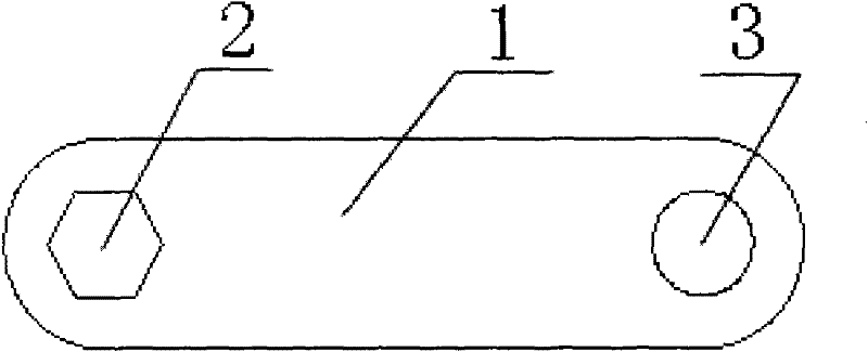
[0020] A fastening wrench for large-diameter high-strength bolts, such as Figure 1 ~ Figure 3 As shown, the specific structure is: including the base plate 1 and the sleeve 4, one end of the base plate 1 is provided with a nut hole 2, the nut hole 2 is a regular hexagonal hole, and the other end of the base plate 1 is provided with a connecting hole 3 for connecting Hole 3 is a circular hole. Both ends of the bottom plate 1 are semicircular, the distance from the center of the nut hole 2 to the outermost edge of the bottom plate 1 at the end of the nut hole 2 is equal to the distance from the opposite side of the nut hole 2, and the distance between the center of the connecting hole 3 and the end of the connecting hole 3 The distance from the outermost edge of the bottom plate 1 is equal to the diameter of the connecting hole 3 . The inner diameter of the sleeve 4 is 105% to 120% of the width of the bottom plate 1, which is 110% in this embodiment, and the sleeve 4 is set ou...


PUM


Abstract

The invention relates to the field of fastening members with heads or rods having special shapes when the connection of an object adopts a bolt connection mode, in particular to a fastening spanner for a large-diameter and high-strength bolt and a use method thereof. The fastening spanner for the large-diameter and high-strength bolt comprises a base plate (1) and is characterized in that a screw cap hole (2) is arranged at one end of the base plate (1) and is a regularly-hexagonal hole; and a connecting hole (3) is arranged at the other end of the base plate (1) and is a round hole. The use method of the fastening spanner for the large-diameter and high-strength bolt is characterized in that the screw cap hole (2) on the base plate (1) is sleeved outside the screw cap of the bolt and is screwed; a sleeve (4) is sleeved outside one end of the connecting hole (3) of the base plate (1) and is screwed; and the sleeve is taken down and a chain block (5) is started for continuously screwing the bolt. The invention has the advantages of wide application range, high construction quality, simpleness in operation, safety and reliability.

Description

technical field [0001] The invention relates to the field of fastening components with special-shaped heads or rods when objects are connected by bolts, in particular to a fastening wrench for large-diameter high-strength bolts and its use method. Background technique [0002] The wheel-spoke tension structure system is a fully tension structure derived from the concept of wheel spokes. The structure is composed of outer ring beams, support columns, flexible cable trusses and inner rings. The outer ring beam is a The space curved beam, the outer ring beam is connected by the compression ring box girder one by one through the flange. The support column under the outer ring beam bears the tensile force; the flexible cable truss is arranged in the upper and lower chords, which is concave in shape, and is composed of flying columns, upper and lower chord cables and vertical cables connecting the upper and lower chords. The flying columns adopt circular steel pipe cross-sections;...

Claims


Application Information

Patent Timeline
Patent Type & Authority Applications(China)
IPC IPC(8): B25B13/06B25B23/00
Inventor 李乘建陈定洪龙钦宇俞桂明
Owner SHANGHAI BAOYE GRP CORP
Why Eureka
Try Eureka