Liquid cooling arrangement for electric

A fluid cooling and machine technology, applied in the direction of cooling/ventilation devices, electromechanical devices, electric components, etc., can solve the problems of setting holes for air passage, impossibility of electric machines, low efficiency, etc.

Active Publication Date: 2012-02-01
TM4 INC
View PDF8 Cites 4 Cited by
  • Summary
  • Abstract
  • Description
  • Claims
  • Application Information

AI Technical Summary

Problems solved by technology

Since air is generally an inefficient cooling fluid, the efficiency of this cooling unit is poor
Additionally, some electric machines operate in environments where it is impossible to provide electric machines with holes to allow the passage of air

Method used


Image

  • Liquid cooling arrangement for electric
  • Liquid cooling arrangement for electric
  • Liquid cooling arrangement for electric

Examples


Embodiment Construction

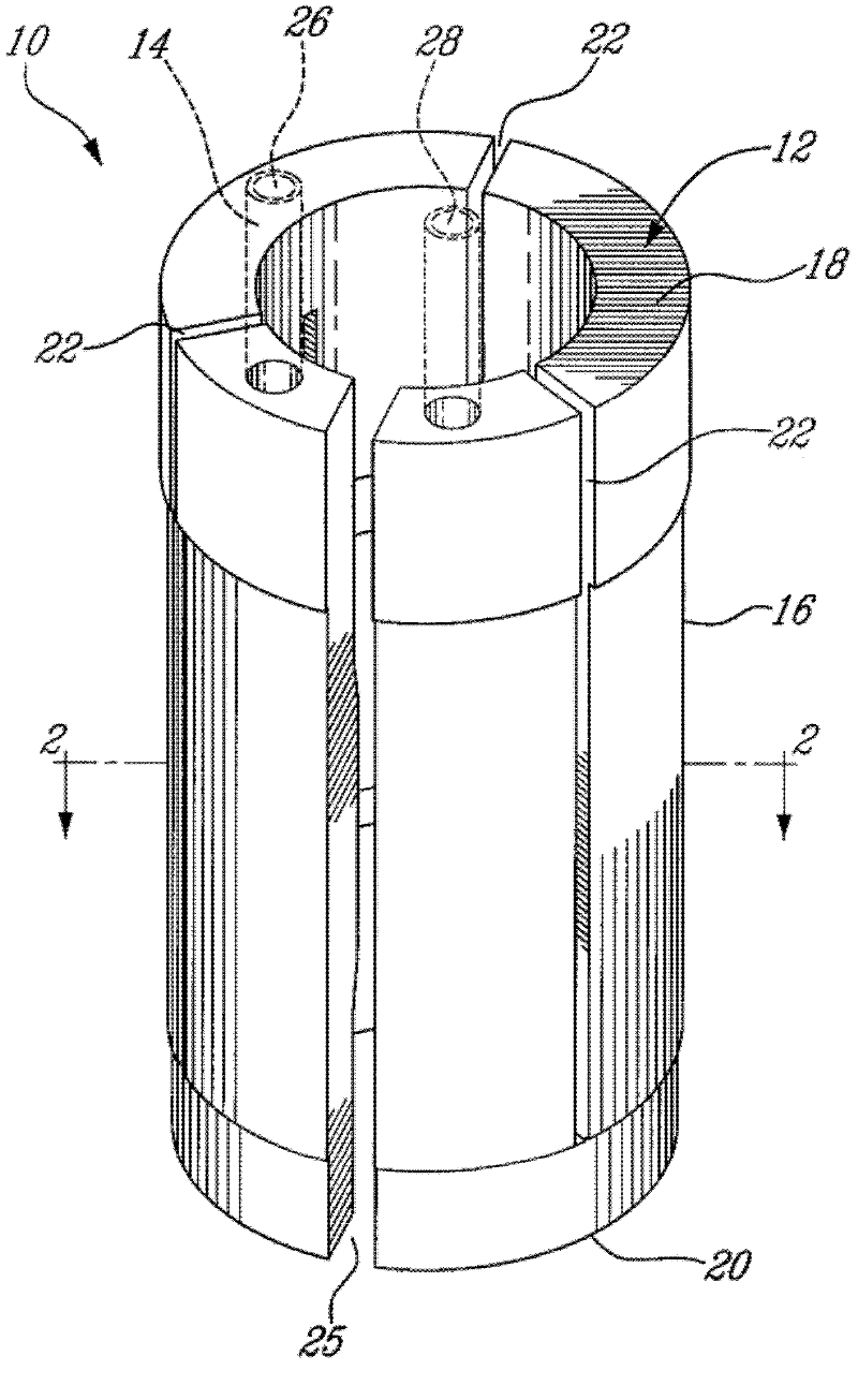
[0034] now turn Figure 1-Figure 6 , the fluid cooling device 10 according to the first exemplary embodiment will be described.

[0035] The fluid cooling device 10 comprises a thermal storage element in the form of a tubular body 12 and a cooling path in the form of a continuous serpentine cooling tube 14 embedded in the tubular body 12 .

[0036] Tubular body 12 is generally C-shaped and includes an outer surface 16 and first and second longitudinal ends 18 and 20 . Three expansion slots 22 are provided from the first longitudinal end 18 and two expansion slots 24 are provided from the second longitudinal end 20 (see figure 2 ). The expansion slot 22 opens towards the first longitudinal end 18 but does not reach the second longitudinal end 20 . On the contrary, if the image 3 As better seen in the bottom plan view of , the expansion slot 24 opens towards the second longitudinal end 20 but does not reach the first longitudinal end 18 .

[0037] The C-shape of the tubul...


PUM


Abstract

A liquid cooling arrangement for electric machines uses a continuous cooling tube associated with a heat storing element. The cooling tube has a serpentine configuration and the heat storing element includes longitudinal slots starting from both longitudinal ends of the heat storing element. Accordingly, it is possible to slightly deform the heat storing element to properly position it into the internal stator of an electric machine. An internal biasing assembly may be used to force the external surface of the heat storing element to the internal surface of the stator.

Description

technical field [0001] This invention relates to electric machines. More specifically, the present invention relates to a fluid cooling device for an electric machine and an electric machine provided with such a fluid cooling device. Background technique [0002] Electric machines, motors or generators are well known in the art. It is also widely known that electric machines generate heat as a by-product and that this heat must be somehow removed from the machine in order to improve the performance of the machine and / or prevent premature degradation or failure as a result. [0003] Electric machines are usually air cooled. This is easily accomplished by providing holes in the body of the machine to force air through there. Such cooling devices are inefficient since air is generally an inefficient cooling fluid. Furthermore, the environment in which some electric machines operate makes it impossible to provide the electric machine with holes to allow the passage of air. ...

Claims


Application Information

Patent Timeline
Patent Type & Authority Applications(China)
IPC IPC(8): H02K9/19
CPCH02K9/22H02K5/20H02K9/227H02K5/203H02K9/193H02K9/225H02K1/20
Inventor M.霍尔G.伯苏克S.比格拉斯B.卡彭蒂尔
Owner TM4 INC
Why Eureka
Try Eureka