
Magnetron

A magnetron and magnetic pole technology, applied in the field of magnetron, can solve the problems of low microwave output efficiency, complex structure, and increased manufacturing cost, and achieve the effects of high microwave output efficiency, convenient process realization, and simple structural design

Active Publication Date: 2014-12-03
GUANGDONG WITOL VACUUM ELECTRONICS MFR
View PDF5 Cites 0 Cited by
  • Summary
  • Abstract
  • Description
  • Claims
  • Application Information

AI Technical Summary

Problems solved by technology

Especially when the oscillation frequency increases, the parasitic oscillation at the end becomes more prominent, which leads to problems such as unstable operation of the magnetron, poor oscillation spectrum and low microwave output efficiency, and even the failure of the magnetron to work.
[0004] In order to avoid the negative impact of the parasitic oscillation at the end of the magnetron, absorbing materials or other filtering devices for the parasitic oscillation mode are usually arranged in the end space; greatly increased cost

Method used


Image

  • Magnetron

Examples


Embodiment Construction

[0012] The specific embodiments of the present invention will be further described below in conjunction with the accompanying drawings.

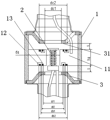
[0013] Such as figure 1 Shown, the present invention is a kind of magnetron, comprises anode part, cathode part, and anode part comprises the anode cylinder 1 of cylinder shape, is fixed on the anode cylinder 1 inner wall surface and is radial some anode blades 11 and places anode The large intersecting ring 12, the small intersecting ring 13 and the antenna coaxial with the anode cylinder 1 in the cylinder 1, the cathode part includes a central pole assembly coaxially assembled with the anode part and a helical filament 2 wound on the central pole assembly , a pair of tapered magnetic poles 3 of soft magnetic material are symmetrically installed on the axial direction of the anode part. The oscillation wavelength of the main oscillation π mode of the present invention is λ, and the oscillation frequency is fo. It is characterized in that th...


PUM


Abstract

The invention relates to a magnetron which comprises an anode part and a cathode part; the anode part comprises an anode tube, anode blades which are fixed on the inner surface of the anode tube, and a large cross ring chain, a small cross ring chain and an output antenna which are arranged in the anode tube; the cathode part comprises a central support rod component and a spiral filament which is wound on the central support rod component; a pair of conical magnetic poles, which are made of soft magnetic materials, is symmetrically arranged in the axial direction of the anode part; the oscillation wavelength of a main oscillation pi mode of the magnetron is lambda, and the frequency is fo; the distance s from the top ends of the anode blades to the bottoms of the conical magnetic poles is between 0.04 lambda to 0.1 lambda; and the heights ha of the anode blades are between 0.14 lambda to 0.20 lambda. According to the invention, the main mode oscillation frequency and the coupling degree of the magnetron basically remain unchanged, so that the oscillation of a parasitic mode on the end is farther from the main mode oscillation frequency, and the magnetron which oscillates stably in the pi mode and has high microwave output efficiency. The product performance is stable, the structural design is simple, the process is convenient to realize and the cost is low.

Description

technical field [0001] The invention relates to a magnetron, in particular to a magnetron in the 5.8GHz frequency band used in microwave ovens or industrial microwave equipment. Background technique [0002] Magnetron is a vacuum electron tube that generates microwaves. Because of its high oscillation efficiency and high microwave output power, it is not only widely used in household microwave ovens, but also widely used as a microwave source for microwave processing equipment such as industrial heating and chemical processing. With the development of microwave technology, higher frequency magnetrons are needed, such as continuous wave magnetrons in the 5.8GHz frequency band, to improve the effect of microwaves and dielectric materials, improve material properties, and provide more effective research on new materials. processing technology. [0003] In a general magnetron, the anode part is a resonant cavity composed of an anode cylinder, a large cross-connected ring, a sma...

Claims


Application Information

Patent Timeline
Patent Type & Authority Patents(China)
IPC IPC(8): H01J25/50H01J23/027
Inventor 王彩育黄启先钟立松陈庆华王贤友
Owner GUANGDONG WITOL VACUUM ELECTRONICS MFR
Learn More