
Signal test simulation device for testing sensor

A technology for signal testing and simulation devices, applied to measuring devices, instruments, etc., to achieve the effects of reducing complexity, reducing the introduction of error signals, and facilitating data playback

Active Publication Date: 2012-02-01
COMAC +1
View PDF5 Cites 8 Cited by
  • Summary
  • Abstract
  • Description
  • Claims
  • Application Information

AI Technical Summary

Problems solved by technology

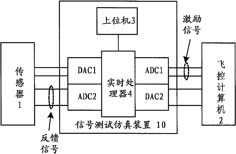
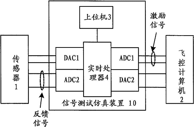
[0003] In order to avoid system confusion, reduce errors and overcome many shortcomings such as inconvenient data playback, the present invention proposes a signal test simulation device for sensors, which is connected in series between the sensor and the flight control computer, which includes a host computer, A real-time processor, a first analog-to-digital converter, a first digital-to-analog converter, a second analog-to-digital converter and a second digital-to-analog converter, the real-time processor and the host computer, the first analog-to-digital converter device, the first digital-to-analog converter, the second analog-to-digital converter and the second digital-to-analog converter are respectively electrically connected; wherein, the excitation signal sent by the flight control computer passes through the first analog The digital converter, the real-time processor and the first digital-to-analog converter are sent to the sensor, and the excitation signal sent by the flight control computer is sent to the sensor through the first analog-to-digital converter and the real-time processor in sequence. to the host computer; correspondingly, the feedback signal of the sensor is sent to the flight control computer through the second analog-to-digital converter, the real-time processor and the second digital-to-analog converter in sequence, and, The feedback signal of the sensor is sent to the host computer sequentially through the second analog-to-digital converter and the real-time processor

Method used


Image

  • Signal test simulation device for testing sensor
  • Signal test simulation device for testing sensor

Examples


Embodiment Construction

[0011] As shown in Figure 1, the signal test simulation device 10 for testing the sensor 1 is connected in series between the differential transformer sensor 1 and the flight control computer 2, and it includes a host computer 3, a real-time processor 4, a first modulus Converter ADC1, first digital-to-analog converter DAC1, second analog-to-digital converter ADC2 and second digital-to-analog converter DAC2, real-time processor 4 and upper computer 3, first analog-to-digital converter ADC1, first digital-to-analog converter The device DAC1, the second analog-to-digital converter ADC2 and the second digital-to-analog converter DAC2 are respectively electrically connected; wherein, the excitation signal sent by the flight control computer 2 passes through the first analog-to-digital converter ADC1, the real-time processor 4 and the first digital-to-analog converter successively. The analog converter DAC1 is sent to the sensor 1, and the excitation signal sent by the flight contro...


PUM


Abstract

The invention discloses a signal test simulation device for a testing sensor. The device is connected in series between a sensor and a fly control computer, and comprises an upper computer, a real-time processor, a first ADC (analogue-digital converter), a first DAC (digital-analogue converter), a second ADC and a second DAC, wherein an excitation signal from the fly control computer is transferred to the sensor through the first ADC, the real-time processor and the first DAC in turn; a feedback signal of the sensor is transferred to the fly control computer through the second ADC, the real-time processor and the second DAC in turn; and the feedback signal of the sensor is transferred to the upper computer through the second ADC and the real-time processor in turn. By adopting the device, the complexity of the test device can be reduced, the introduction of error signals can be reduced as much as possible, and the test accuracy is improved; and moreover, the sensor original voltage signal acquired by the device can be conveniently subjected to data playback through a signal simulation function so as to ensure the primitiveness and consistency of the test data to the greatest degree.

Description

technical field [0001] The invention relates to a signal test simulation device, in particular to the test and simulation of sensor signals applied in a flight control system. Background technique [0002] LVDT (Linear Variable Differential Transformer) or RVDT (Rotary Variable Differential Transformer) sensors are widely used in fly-by-wire flight control systems due to their high precision, stable performance, and easy integration. The displacement is sent to the flight control computer, which calculates the control rate and then controls the terminal's actuating mechanism to actually control the aircraft. As the input of the entire flight control system, the sensor is very important in the function verification test and data analysis of the flight control system. Therefore, the test of the sensor itself has become a topic. At present, the test method for this type of sensor itself is to pass the sensor signal through a dedicated signal conditioning board, which will cond...

Claims


Application Information

Patent Timeline
IPC IPC(8): G01B21/02G01B21/22
Inventor 田剑波赵京洲王兴波李飞张勇陈骐
Owner COMAC
Learn More