Heat exchanger structure and its assembly process

An assembly process, heat exchanger technology, applied in heat exchange equipment, lighting and heating equipment, tubular components, etc. Product quality, the effect of ensuring welding quality

Inactive Publication Date: 2016-03-02
LG ELECTRONICS (TIANJIN) APPLIANCES CO LTD
View PDF8 Cites 4 Cited by
  • Summary
  • Abstract
  • Description
  • Claims
  • Application Information

AI Technical Summary

Problems solved by technology

[0006] However, for the existing radiator structure, the fixed connection between the fin and the flat tube adopts high-temperature welding in a welding furnace, and the welding temperature is above 500°C. The whole production process is complicated and the cost is increased; The uniformity is very large, so the stability of the solder layer is not high after welding, which will cause some parts that are originally intended to be joined may not be joined continuously, which will make the brazed part worse, such as fin separation, which in turn will lead to a decline in product quality

Method used


Image

  • Heat exchanger structure and its assembly process
  • Heat exchanger structure and its assembly process
  • Heat exchanger structure and its assembly process

Examples


Embodiment Construction

[0031] The present invention will be further described in detail below in conjunction with the drawings and specific embodiments:

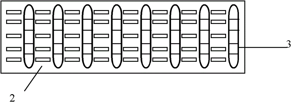
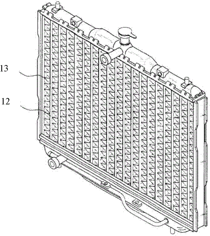
[0032] Such as Figure 4-8 Shown is the first embodiment of the present invention. As shown in the figure, the fin 13 is a rectangular aluminum sheet with a plurality of sets of punching holes 31 evenly spaced thereon. The punching holes 31 are opened along the length of the rectangular fin. The said punching hole 31 facilitates the flow of airflow in it to enhance the heat dissipation effect of the heat sink. A rectangular pipe groove 32 with rounded corners is opened between the two sets of punching holes 31. The width of the pipe groove 32 is slightly larger than the thickness of the flat pipe 22 to be in place, so that the flat pipe 22 can enter the pipe groove 32 smoothly.

[0033] Further, flanges are provided around the pipe groove 32 to limit the distance between two adjacent fins 13.

[0034] As attached Figure 5 As shown, the flat tube 22 of...


PUM


Abstract

The invention discloses a heat exchanger structure. The heat exchanger structure comprises fins and a flat pipe connected with the fins in a locating manner, wherein grooves are concavely formed inwards on two side surfaces of the flat pipe and extend along the length direction of the flat pipe. The invention also discloses an assembly process of the heat exchanger structure, comprising the following steps of: (1) sequentially piling and fixing the fins; (2) embedding a lug boss of a welding material sheet into each groove in a matching manner, and connecting the welding material sheet and the flat pipe in the locating manner; (3) locating the flat pipe connected with the welding material sheet in the locating manner and the fins; and (4) placing the flat pipe and the fins in a brazing furnace to weld. By using the heat exchanger structure and the assembly process thereof, the welding material uniformity is improved, a connecting region is beneficially formed by the welding material around a contact point of the fins and the flat pipe, the welding strength is improved, and because the grooves are arranged in the middle of the flat pipe, the density of microchannels in the center of the flat pipe is reduced, the phenomenon, such as freezing and the like caused by too low temperature in the center is improved, the pipeline groove radius can be correspondingly increased while the welding quality is ensured, and a flanging height is beneficially designed.

Description

Technical field [0001] The invention relates to a condenser, in particular to a heat exchanger structure and an assembly method thereof. Background technique [0002] When the room air conditioner is operating under cooling conditions, indoor air flows through the evaporator to reduce the temperature. At the same time, since the surface temperature of the evaporator is generally significantly lower than the dew point temperature of the air, part of the moisture in the air will be precipitated when the air flows over the surface of the evaporator, thereby forming condensed water on the surface of the evaporator. The condensed water on the surface of the evaporator should be drained in time. If the condensed water accumulates more on the surface of the evaporator, it will block the air flow path, increase the air flow resistance, and reduce the efficiency of the evaporator: water droplets may also be blown in The indoor conditions caused the quality of the air conditioner to be su...

Claims


Application Information

Patent Timeline
Patent Type & Authority Patents(China)
IPC IPC(8): F28F1/20F28F1/02
Inventor 崔静车金峰
Owner LG ELECTRONICS (TIANJIN) APPLIANCES CO LTD
Why Eureka
Try Eureka