


Quick Research
Generate reliable direction feasibility study reports for your R&D in just a few steps.

Technical Q&A
Discover and master advanced knowledge NOW. Basics, ideas, possibilities, all at once.

Find Solutions
As an expert in R&D theories, this can generate solutions to your technical problems instantly.

Evaluate Feasibility
Analyze your overall solution with one click, know your potential R&D risks in advance.

Monitor Landscape
Get weekly tech updates, stay abreast of the latest tech innovations and key insights.
Compressor for increasing volumetric efficiency of cylinder
A cylinder volume and compressor technology, applied in mechanical equipment, machines/engines, liquid fuel engines, etc., can solve problems affecting compressor performance, low cylinder volume efficiency, and insufficient utilization of cylinder volume area 1d, etc., to eliminate Effect of suction clearance volume, improvement of suction efficiency and indication efficiency, and performance improvement
- Summary
- Abstract
- Description
- Claims
- Application Information
AI Technical Summary
Problems solved by technology
Method used
Image

Examples
Embodiment 1
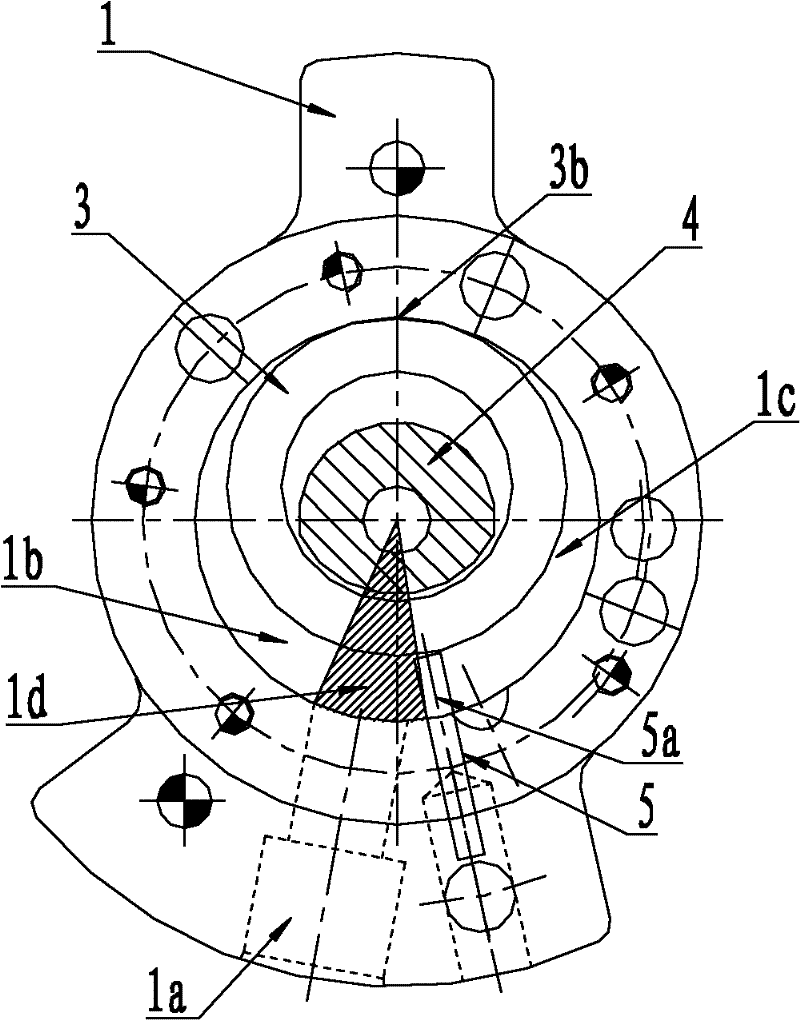
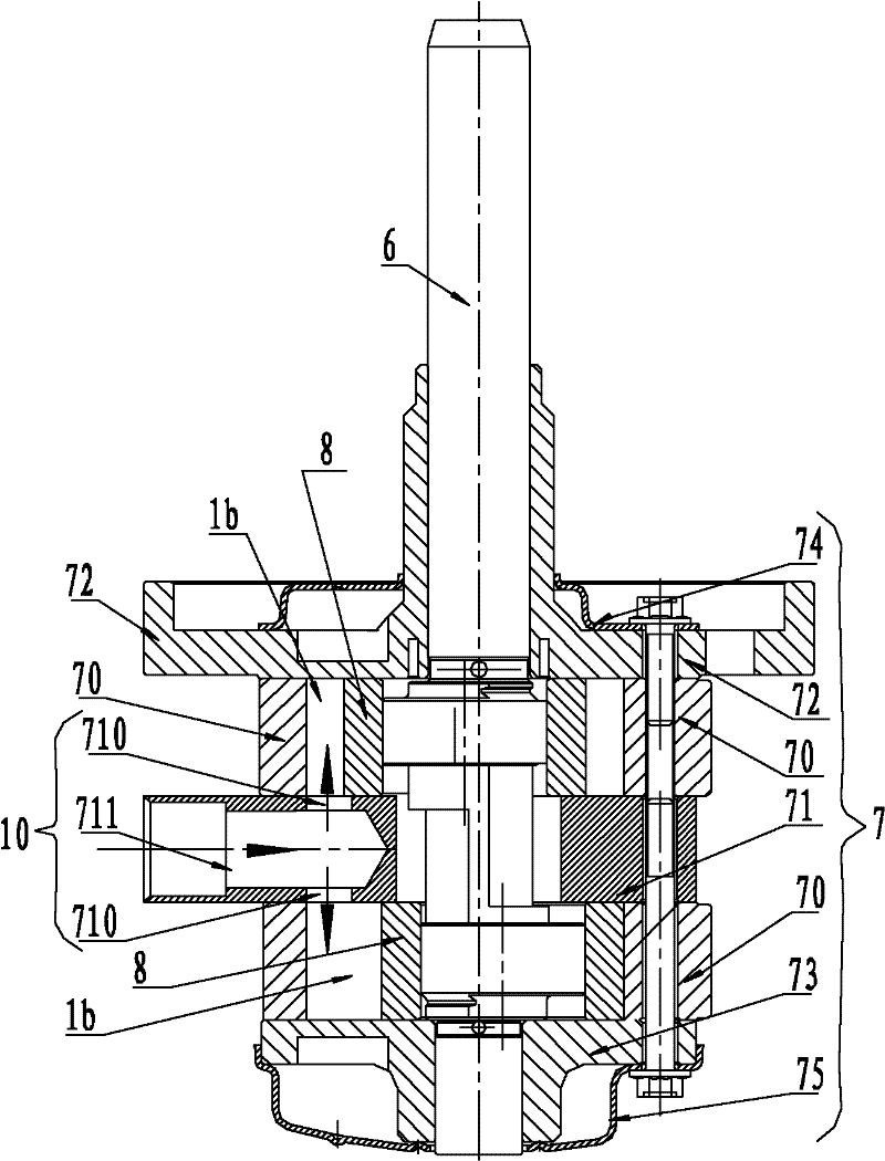
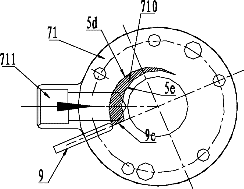
[0019] Such as figure 2 and image 3 As shown, a compressor that improves cylinder volumetric efficiency, the compressor is a two-cylinder compressor, and the two-cylinder compressor includes a motor 6 (only the crankshaft of the motor is shown in the figure), a cylinder assembly 7 and eccentric compression rollers 8. The cylinder block assembly 7 includes a cylinder 70 (double cylinder), a partition 71 arranged between the double eccentric compression rollers of the double cylinder, and an upper flange 72 and a lower flange 73 covering both ends of the cylinder, the upper and lower Flanges (72, 73) are respectively equipped with an upper muffler 74 and a lower muffler 75 matched with it; the crankshaft of the motor 6 is equipped with an eccentric compression roller 8 rotating in the cylinder 70, and an eccentric compression roller 8 is installed in the cylinder 70. The sliding piece 9 matched with the roller 8; the air intake hole 10 communicated with the working chamber of...
Embodiment 2
[0022] Such as Figure 4 and Figure 5 As shown, the compressor is a single-cylinder compressor, which includes a motor 6 (only the crankshaft of the motor is shown in the figure), a cylinder assembly 7 and an eccentric compression roller 8, and the cylinder assembly 7 includes a cylinder 70 ( Single cylinder) and the upper flange 72 and the lower flange 73 that cover the two ends of the cylinder, the upper and lower flanges (72, 73) are respectively equipped with an upper muffler 74 and a lower muffler 75 that cooperate with it; The crankshaft is equipped with an eccentric compression roller 8 that rotates in the cylinder 70, and a sliding piece 9 that cooperates with the eccentric compression roller 8 is installed in the cylinder 70; The air intake hole 10', the side end surface of the rotating eccentric compression roller 8 cooperates with the air intake hole 10' and can periodically close the passage between the air intake hole 10' and the working chamber of the cylinder ...
Embodiment 3
[0025] Such as Figure 6 and Figure 7 As shown, the only difference between this embodiment and the second embodiment is that the side wall of the lower flange 73 is provided with an air intake hole 10 "communicated with the working chamber of the cylinder 70, and the side end surface of the rotating eccentric compression roller 8 Cooperate with the air intake hole 10 "and can periodically close the passage between the air intake hole 10" and the working chamber of the cylinder 70; The rotation track line (7d, 7e) of the high point of the outer circle and the high point of the inner hole that the top of the center line of the slide piece 9 collides with is vertically projected on the wall of the lower flange 73 to form a semi-crescent closed maximum area air intake area, any shape or individual The number of air inlet holes can fall within this range; the air inlet hole 10 "can be crescent-shaped, also can be other shapes, can be one or more holes equally. In this example, t...
PUM
 Abstract
Description
Claims
Application Information
 - R&D Engineer
- R&D Manager
- IP Professional
- Industry Leading Data Capabilities
- Powerful AI technology
- Patent DNA Extraction
Browse by: Latest US Patents, China's latest patents, Technical Efficacy Thesaurus, Application Domain, Technology Topic, Popular Technical Reports.
© 2024 PatSnap. All rights reserved.Legal|Privacy policy|Modern Slavery Act Transparency Statement|Sitemap|About US| Contact US: help@patsnap.com