
Returned alumina conveying distribution structure

A configuration structure, alumina technology, applied in the field of alumina configuration structure, can solve the problems of excessive purification system, damage to raw material delivery balance, environmental hazards around the enterprise, etc., to achieve the effect of ensuring emission targets

Inactive Publication Date: 2014-04-09
沈阳铝镁科技有限公司
View PDF3 Cites 0 Cited by
  • Summary
  • Abstract
  • Description
  • Claims
  • Application Information

AI Technical Summary

Problems solved by technology

However, this will destroy the balance of raw material delivery in the electrolytic flue gas purification system, resulting in an increase in the addition of fluorine-loaded alumina in the purification reactor, and a decrease in the addition of fresh alumina. environmental hazard

Method used


Image

  • Returned alumina conveying distribution structure
  • Returned alumina conveying distribution structure
  • Returned alumina conveying distribution structure

Examples


Embodiment 1

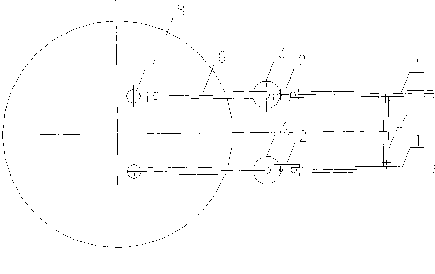
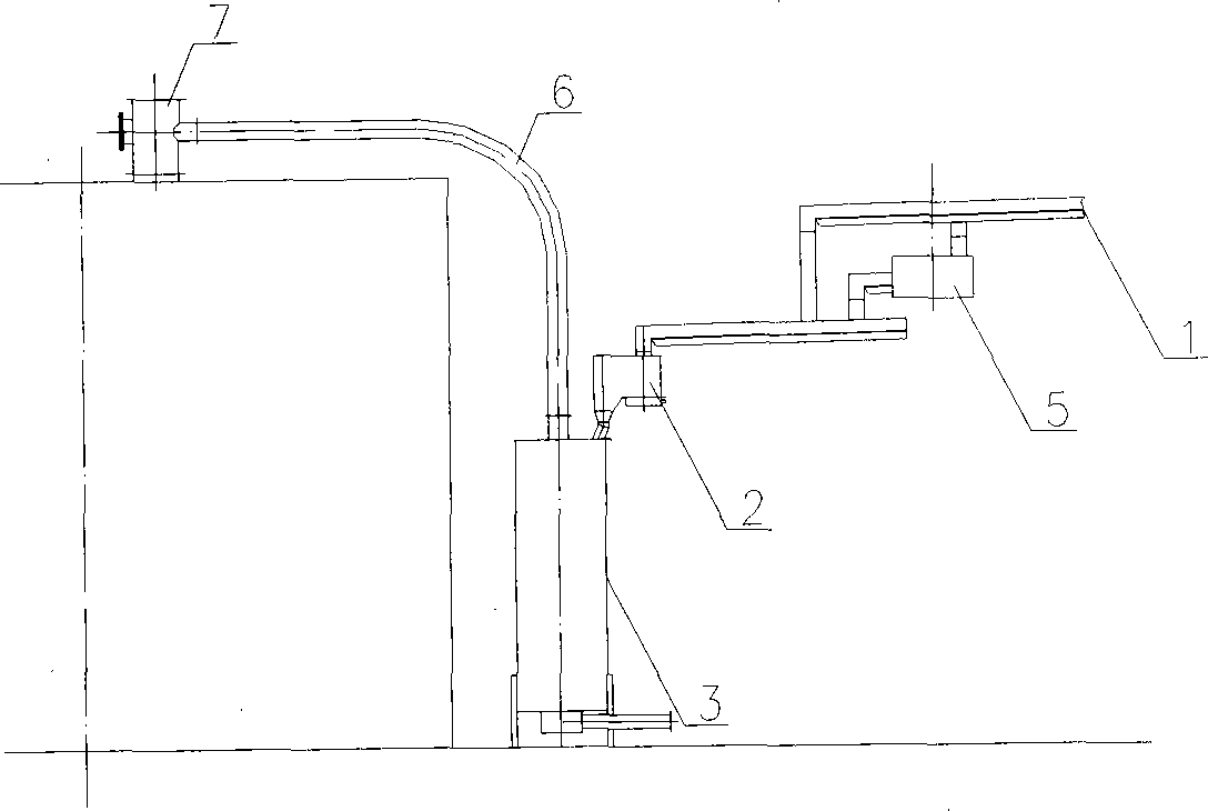
[0015] Such as figure 1 The conveying arrangement structure of returning alumina of the present invention shown in the present invention comprises two return chutes 1, and the two return chutes are respectively connected with the material lifting device 3, and the material lifting device 3 is a pneumatic lifter, and the return chute 1 is provided with Connect the chute 4, and set a miscellaneous removal box 2 between the return chute 1 and the material lifting device 3. The miscellaneous removal box has the function of separating impurities; the material lifting device 3 is connected to the top of the storage bin 8 through the feeding pipe 6, and the feeding pipe A feeder 7 is provided between 6 and the top of the storage bin 8 .

Embodiment 2

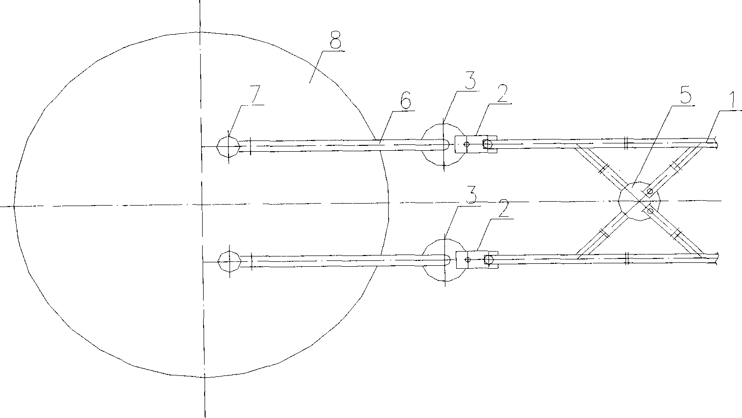
[0017] In Embodiment 1, a diverter 5 is provided between the two return chutes 1, and the diverter can change the flow direction of the alumina material; the material lifting device is a pressure tank lifting device, and the others are the same as in Embodiment 1.

Embodiment 3

[0019] There are three return chutes in Embodiment 1, and a connection chute 4 is provided between the three return chutes, and the others are the same as in Embodiment 1.


PUM


Abstract

The invention relates to an alumina distribution structure, especially to a returned alumina conveying distribution structure in an electrolytic flue gas purification system. The returned alumina conveying distribution structure comprises returning chutes which are connected with material lifting devices. A connection chute or a steering gear is disposed between the returning chutes. Impurity removing boxes are disposed between the returning chutes and the material lifting devices. The invention has the following advantages and effects: by changing the returned alumina conveying distribution structure in the electrolytic flue gas purification system, the connection chute or the steering gear is disposed between the returning chutes, so as to make the alumina lifting devices to alternate with each other and accomplish continuous and stable operation of the returned alumina conveying system; the impurity removing box is used to remove impurities in alumina, thus guaranteeing the discharging index of the electrolytic flue gas purification system.

Description

technical field [0001] The invention relates to an alumina arrangement structure, in particular to a transport arrangement structure for returning alumina in an electrolytic flue gas purification system. Background technique [0002] In the electrolytic flue gas purification system, the fluorine-loaded alumina usually comes out of the lower hopper of the dust collector and enters the pneumatic chute. Enter the air lift or pressure tank through the pneumatic chute, and drive the fluorine-loaded alumina into the storage bin through the material lifting device. When the electrolytic production capacity is not large, the purification and dust collectors are generally configured in a single row, and the diameter of the fluorine-loaded alumina storage bin is not too large. At this time, a pneumatic lifting device is often used to lift the material. With the expansion of single-series electrolysis production capacity, the electrolysis flue gas purification system is also expanding...

Claims


Application Information

Patent Timeline
Patent Type & Authority Patents(China)
IPC IPC(8): C25C3/14C25C3/06
Inventor 张国斌宋海琛李佰福丁大勇赵冰洋李斌
Owner 沈阳铝镁科技有限公司
Learn More