Device for preventing hot air from flowing back in water shield of aerator and impeller aerator

A hot air return, waterproof cover technology, applied in water aeration, water/sludge/sewage treatment, sustainable biological treatment, etc. The effect of reducing the cost of the machine, preventing oil leakage from polluting the fish pond, and having a simple structure

Inactive Publication Date: 2012-02-01
吴为国
View PDF8 Cites 4 Cited by
  • Summary
  • Abstract
  • Description
  • Claims
  • Application Information

AI Technical Summary

Problems solved by technology

[0002]Aerator is a life-saving and boosting equipment for fish and shrimp in aquaculture. The existing mechanical aerators mainly include waterwheel type, impeller type and sprayer type. There are three types of water type. The existing aerator motor has a waterproof cover, and the air in the waterproof cover circulates or part of the air circulates inside. The heat dissipation condition is not good, and the motor cannot work at full load, especially the bearing in the upper end cover of the motor. Relatively easy to damage; the existing impeller type aerators all have gear reduction mechanisms, which are complex in structure, heavy and costly

Method used


Image

  • Device for preventing hot air from flowing back in water shield of aerator and impeller aerator
  • Device for preventing hot air from flowing back in water shield of aerator and impeller aerator
  • Device for preventing hot air from flowing back in water shield of aerator and impeller aerator

Examples


Embodiment Construction

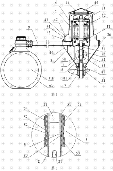
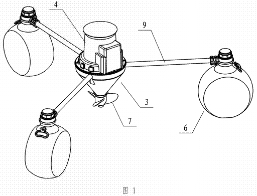
[0052] Below in conjunction with accompanying drawing, the present invention will be further described with specific embodiment, see Figure 1-21 :

[0053]The device for preventing hot air backflow in the waterproof cover of the aerator is mainly composed of a motor 1, a waterproof cover 4, an air inlet 45, and an air outlet window 41. The motor 1 is installed vertically, and a cooling fan is installed on the motor shaft protruding from the upper end of the motor. 13. There is a fan cover 12 outside the cooling fan 13, a plurality of cooling fins on the motor casing, and a waterproof cover 4 outside. There is an air inlet 45 on the waterproof cover, and there are air outlet windows 41 around the lower part of the waterproof cover. The waterproof cover 4 and There is an isolation device between the motors 1 to prevent the motor hot air from flowing back upwards into the motor fan cover 12, so that the hot air formed after the heat exchange between the cooling fan and the heat ...


PUM


Abstract

The invention belongs to the technical field of aerators, and relates to an impeller aerator provided with a device for preventing hot air from flowing back in a water shield. A motor is arranged in a shell consisting of a conical body and the water shield; a supporting base of the motor is connected with the shell; a motor shaft is connected with an impeller shaft and vertically extends into water downward; a motor body is positioned over the horizontal pane; an isolation device for preventing the hot air of the motor from upward flowing back and entering a fan guard of the motor is arranged between the water shield and the motor so as to ensure that the hot air formed after the heat exchange of a cooling fan and radiating fins is not returned to the fan guard of the motor and the temperature of the motor is greatly reduced; the supporting base is connected with supporting rods; and the other end of each of the supporting rods is provided with a floating body respectively. The complete machine floats on the water surface to work through the floating bodies, and a water body lifted by an impeller is guided to various directions by using the conical body so as to ensure that lower-layer water fills a vacancy, so that the aim of oxygen increase is fulfilled through the convection of the water body. Structures such as gears, reduction gearboxes and the like which are required in the prior art are abandoned, lubricating oil is not required to be filled, the oil leakage is effectively prevented from polluting fishing ponds, and the production cost is reduced.

Description

technical field [0001] The invention relates to an aerator, in particular to an impeller type aerator with a device for preventing hot air backflow in a waterproof cover. Background technique [0002] The aerator is a life-saving and stimulating equipment for fish and shrimp in aquaculture. The existing mechanical aerators mainly include three types: waterwheel type, impeller type and water spray type. The existing aerator motor has waterproof Cover, the air circulation or part of the air circulation in the waterproof cover, the heat dissipation condition is not good, the motor cannot work at full load, especially the bearing in the upper end cover of the motor is relatively easy to damage; the existing impeller aerators have gears The deceleration mechanism has complex structure, heavy weight and high cost. Contents of the invention [0003] The purpose of the present invention is to solve the deficiency of the existing aerator, and provide a device and an impeller type ...

Claims


Application Information

Patent Timeline
Patent Type & Authority Applications(China)
IPC IPC(8): A01K63/04C02F7/00
CPCY02W10/10
Inventor 吴为国
Owner 吴为国
Why Eureka
Try Eureka