Multi-function radar device
A composite function, radar device technology, applied in measurement devices, radio wave reflection/re-radiation, utilization of re-radiation, etc., can solve problems such as insufficient adjustment, infrared light-receiving lens portion 914, etc.
- Summary
- Abstract
- Description
- Claims
- Application Information
AI Technical Summary
Problems solved by technology
Method used
Image
Examples
no. 1 Embodiment approach
[0042] figure 1 The shown composite function radar device has a signal processing part 6, a frequency modulation signal generating part 8, a high-frequency signal generating part 9, a high-frequency signal branching part 10, an intermittent stop signal generating part 7, a sending intermittent stop switch 11, a sending signal amplifying part 12, circulator part 2, transceiver antenna part 1, received signal amplifying part 3, frequency conversion part 4, beat signal amplifying part 5.
[0043] The frequency modulation signal generation unit 8 outputs a control voltage for performing frequency modulation to the high frequency signal generation unit 9 under the control of the signal processing unit 6 . The high-frequency signal generator 9 generates a high-frequency signal, and outputs the high-frequency signal frequency-modulated by the control voltage output from the frequency modulation signal generator 8 as a transmission signal.
[0044] The transmission signal output fro...
no. 2 Embodiment approach
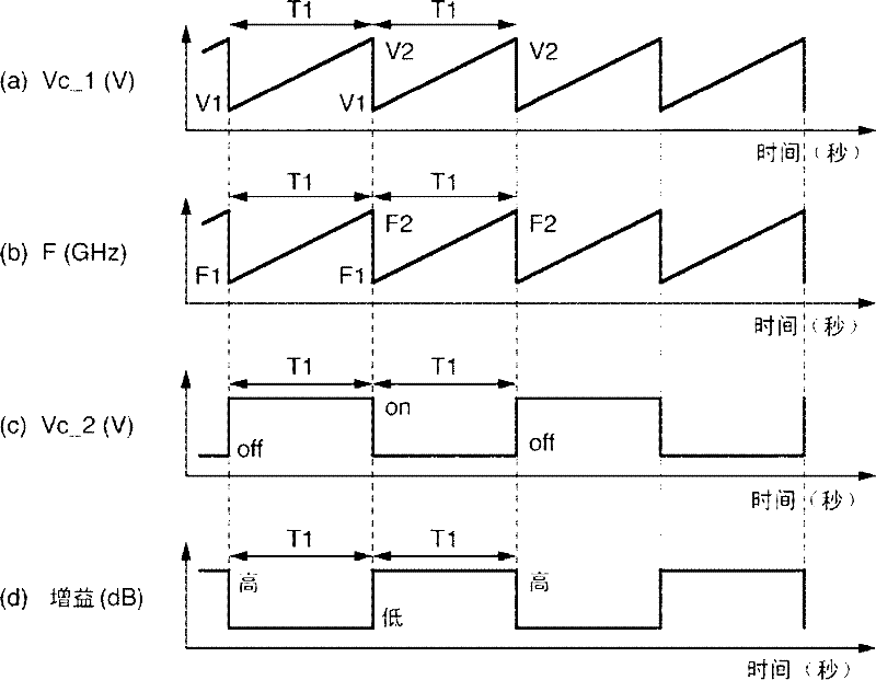
[0063] In this embodiment, a gain adjustment unit 300 is provided instead of the received signal amplifying unit 3 in the first embodiment. Components having the same functions as those in the first embodiment are given the same reference numerals, and description thereof will be omitted.
[0064] image 3 The illustrated gain adjustment unit 300 changes the gain for amplifying the received signal when receiving a reflected wave from the target object 13 and when receiving a radiation wave from the target object 13, and outputs the gain to the frequency converting unit 4. .
[0065] The gain adjustment unit 300 has a first reception signal switching switch 301 , a first reception signal amplification unit 302 , a second reception signal amplification unit 303 , a second reception signal switching switch 304 , and a gain switching signal generation unit 305 . The first received signal amplifying section 302 and the second received signal amplifying section 303 are preset to h...
no. 3 Embodiment approach
[0076] In this embodiment, a measurement noise switching unit 200 is provided between the circulator unit 2 and the reception signal amplifying unit 3 in the first embodiment. Components having the same functions as those in the first embodiment are given the same reference numerals, and description thereof will be omitted.
[0077] Figure 5 The shown measurement noise switching unit 200 switches and outputs the radiation wave from the target object 13 and the thermal noise inside the complex function radar device while the transmission signal is not being transmitted.
[0078] The measurement noise switching unit 200 has a reception signal switching switch 201 and a measurement noise switching signal generation unit 202 . The control voltage from the measurement noise switching signal generation unit 202 under the control of the signal processing unit 60 is input to the reception signal switching switch 201 . The reception signal selection switch 201 switches the signal pa...
PUM
 Abstract
Description
Claims
Application Information
 - R&D
- Intellectual Property
- Life Sciences
- Materials
- Tech Scout
- Unparalleled Data Quality
- Higher Quality Content
- 60% Fewer Hallucinations
Browse by: Latest US Patents, China's latest patents, Technical Efficacy Thesaurus, Application Domain, Technology Topic, Popular Technical Reports.
© 2025 PatSnap. All rights reserved.Legal|Privacy policy|Modern Slavery Act Transparency Statement|Sitemap|About US| Contact US: help@patsnap.com


