
Cable connector assembly

一种线缆连接器、组件的技术,应用在连接、连接装置的零部件、减轻导线连接处应力的装置等方向,能够解决不能匹配连接器、线缆连接器组件数据传输速率不能满足需求等问题,达到高数据传输速率的效果

Inactive Publication Date: 2012-01-25
FOXCONN (KUNSHAN) COMPUTER CONNECTOR CO LTD +1
View PDF4 Cites 2 Cited by
  • Summary
  • Abstract
  • Description
  • Claims
  • Application Information

AI Technical Summary

Problems solved by technology

[0002] As the industry's requirements for the data transmission rate in the server are getting faster and faster, the data transmission rate of the cable connector assembly applied to the outside of the server and docked with the connector inside the server can no longer meet the demand
In addition, with the development of server miniaturization, its internal space will gradually become smaller, and the connectors installed on the internal board of the server will develop towards a low and narrow type, so that more connectors can be installed on the board, while the current application A cable connector assembly that mates externally to a connector inside the server will appear wider than the connector on the server's internal board

Method used


Image

  • Cable connector assembly
  • Cable connector assembly
  • Cable connector assembly

Examples


Embodiment Construction

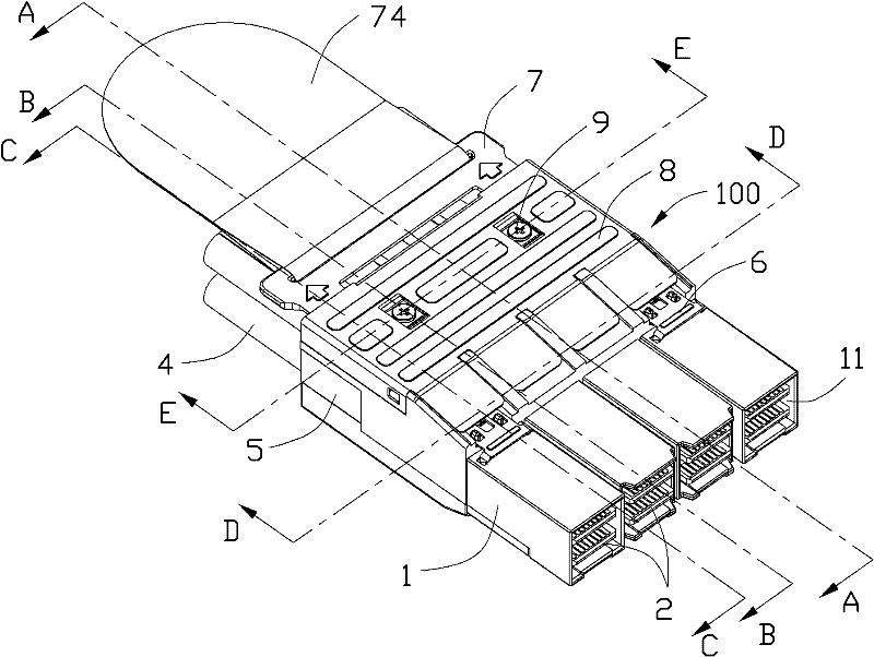
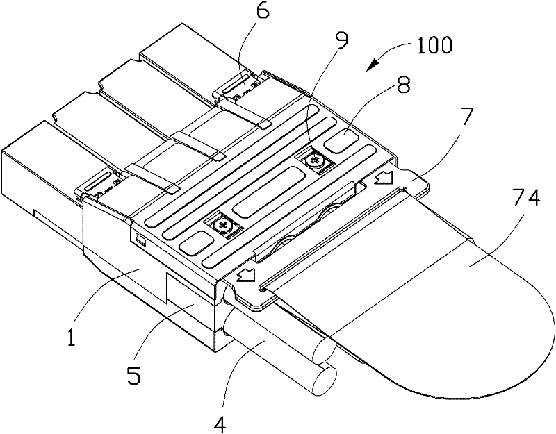
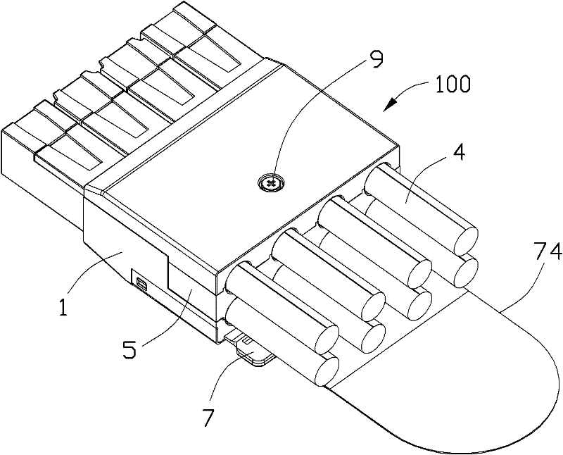
[0017] see Figure 1 to Figure 9 The cable connector assembly 100 of the present invention includes a main body 1 having four horizontally spaced accommodation spaces 11, two printed circuit boards 2 arranged in parallel and spaced intervals along the up and down direction, and arranged in the accommodation spaces 11 of each main body 1. Between the two printed circuit boards 2 in the accommodation space 11 of each body 1 and the spacer 3 that is positioned and matched with the body 1, and the rear ends of a pair of printed circuit boards 2 in the accommodation space 11 of each body 1 are electrically connected respectively. Two cables 4 that connect and extend backwards from the body 1, a strain relief block 5 installed at the inner rear end of the body 1 and spaced apart every two cables 4, and positioning the body 1 and the strain relief block 5 together The positioning part 9. In addition, the cable connector assembly 100 also includes two latches 6 arranged on the upper ...


PUM


Abstract

The invention discloses a cable connector assembly (100) which comprises a body (1) with a plurality of accommodating spaces (11) which are transversely arranged at intervals and extend in the front-back direction, two printed circuit boards (2) which are accommodated in each accommodating space of the body, are mutually positioned in parallel with the body and are arranged at intervals, two lock catch members (6) which are assembled on the upper surface of the body, a drawing member (7) which is connected with the lock catch members and is capable of driving the two lock catch members, a stress relieving block (5) which is arranged at the rear end of the body, and a plurality of cables (4) which extend into the accommodating spaces of the body from rear to front and are electrically connected with the printed circuit board, wherein the body comprises an upper cover body (15) and a lower cover body (16). The cable connector assembly also comprises a plurality of first and second positioning members (91, 92) assembled on the body, wherein the first positioning members are used for respectively positioning the upper cover body and the lower cover body with the stress relieving block along a vertical opposite direction, and the second positioning members are used for positioning the upper cover body and the stress relieving block with the lower cover body along the direction from upside to downside.

Description

【Technical field】 [0001] The invention relates to a cable connector assembly, in particular to a cable connector assembly with a low and narrow butt joint surface. 【Background technique】 [0002] As the industry requires faster and faster data transmission rates in the server, the data transmission rate of the cable connector assembly applied to the outside of the server and docked with the connector inside the server can no longer meet the demand. In addition, with the development of server miniaturization, its internal space will gradually become smaller, and the connectors installed on the internal board of the server will develop towards a low and narrow type, so that more connectors can be installed on the board, while the current application A cable connector assembly that mates externally to a connector inside the server would appear wider than a connector on a board inside the server. [0003] Therefore, there is a need for an improved cable connector assembly to ov...

Claims


Application Information

Patent Timeline
Patent Type & Authority Applications(China)
IPC IPC(8): H01R13/629H01R13/648H01R13/58
CPCH01R13/6658H01R13/6275H01R24/60H01R13/6335H01R13/582H01R13/6586
Inventor 吴荣发
Owner FOXCONN (KUNSHAN) COMPUTER CONNECTOR CO LTD
Learn More