Two-dimensional dynamic target capturing system

A dynamic target and subsystem technology, applied in the system field of two-dimensional capture of dynamic targets, can solve problems such as short capture time, difficult realization, and reduced capture success rate, and achieve the effect of increasing the success rate and reducing the area

Active Publication Date: 2012-01-18
北京国科环宇科技股份有限公司
View PDF4 Cites 17 Cited by
  • Summary
  • Abstract
  • Description
  • Claims
  • Application Information

AI Technical Summary

Problems solved by technology

Rectangular helical scanning combines the advantages of rectangular scanning and helical scanning. The scanning interval overlaps less, and there is no missed scanning area. It is easier to implement, and the average capture time is shorter than rectangular scanning, but there is still the problem of low capture success rate.
The movement trajectory of the beacon light in the rose scan is generated by the rose function. In this scan mode, the jitter of the beacon light generating device has little influence on the capture success rate, but it is difficult to implement, and there are still missed scan areas.
Lissajous scanning can effectively scan the entire capture field of view area, the capture time is short, and the scanning efficiency is high, but it is difficult to implement, and there are still missed scanning areas
[0004] In the existing schemes for capturing dynamic targets, the success rate of capture may be reduced due to the missing scan area in the existing scanning methods; in addition, the existing scanning methods also have the problems of difficult implementation and long capture time , the existing capture scheme needs to be further improved

Method used


Image

  • Two-dimensional dynamic target capturing system
  • Two-dimensional dynamic target capturing system
  • Two-dimensional dynamic target capturing system

Examples


Embodiment Construction

[0024] In order to make the object, technical solution and advantages of the present invention clearer, the present invention will be further described in detail below in conjunction with the embodiments and accompanying drawings.

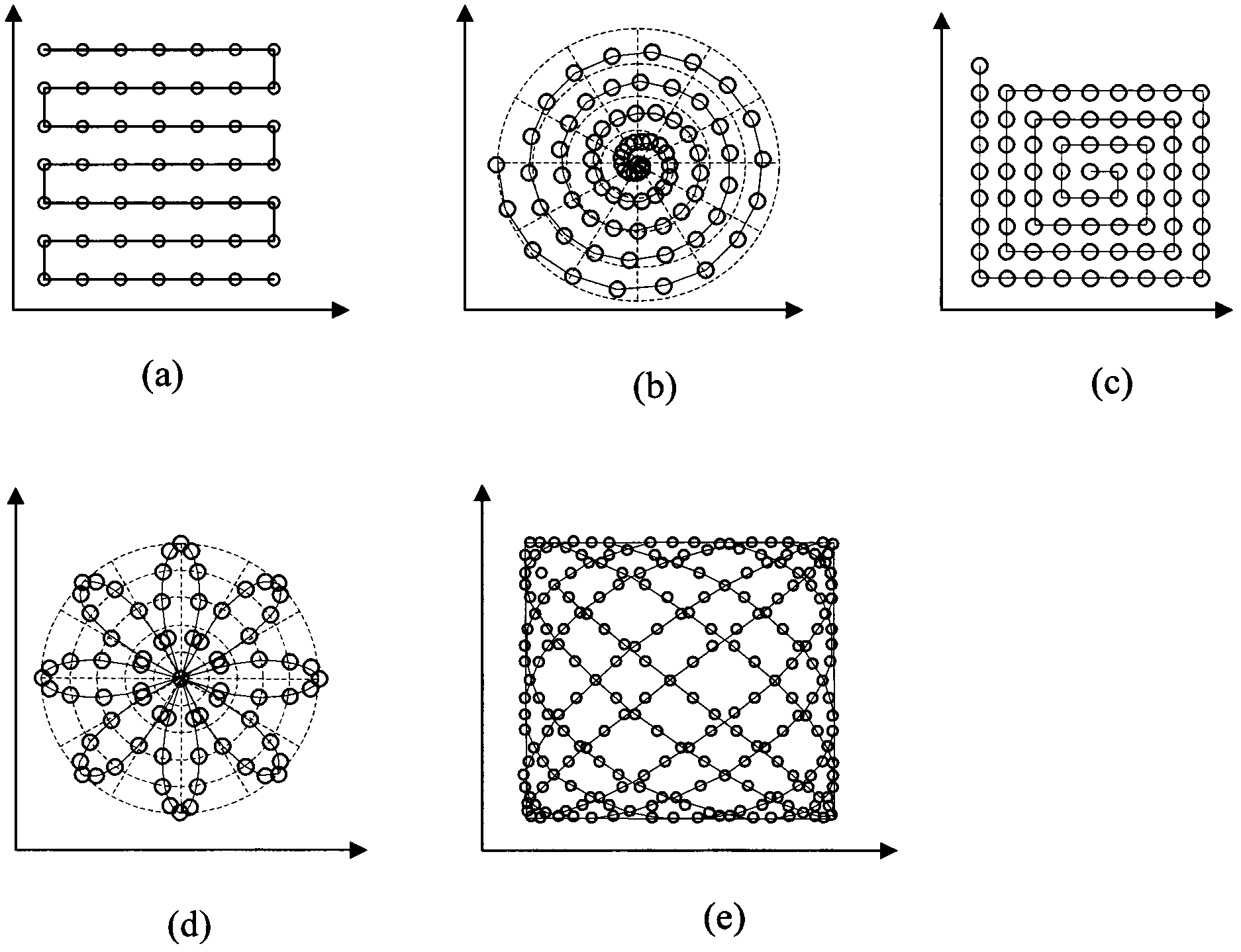
[0025] The present invention is a scheme for capturing dynamic targets in two-dimensional space; in order to express clearly, the first dimension direction and the second dimension direction of the two-dimensional space mentioned in the method of the present invention are first defined, if the first dimension direction of the two-dimensional space If the one-dimensional direction is the vertical direction, then the second-dimensional direction is the horizontal direction, and if the first-dimensional direction of the two-dimensional space is the horizontal direction, then the second-dimensional direction is the vertical direction. The beacon light of the present invention is a light spot used to track and capture dynamic targets.
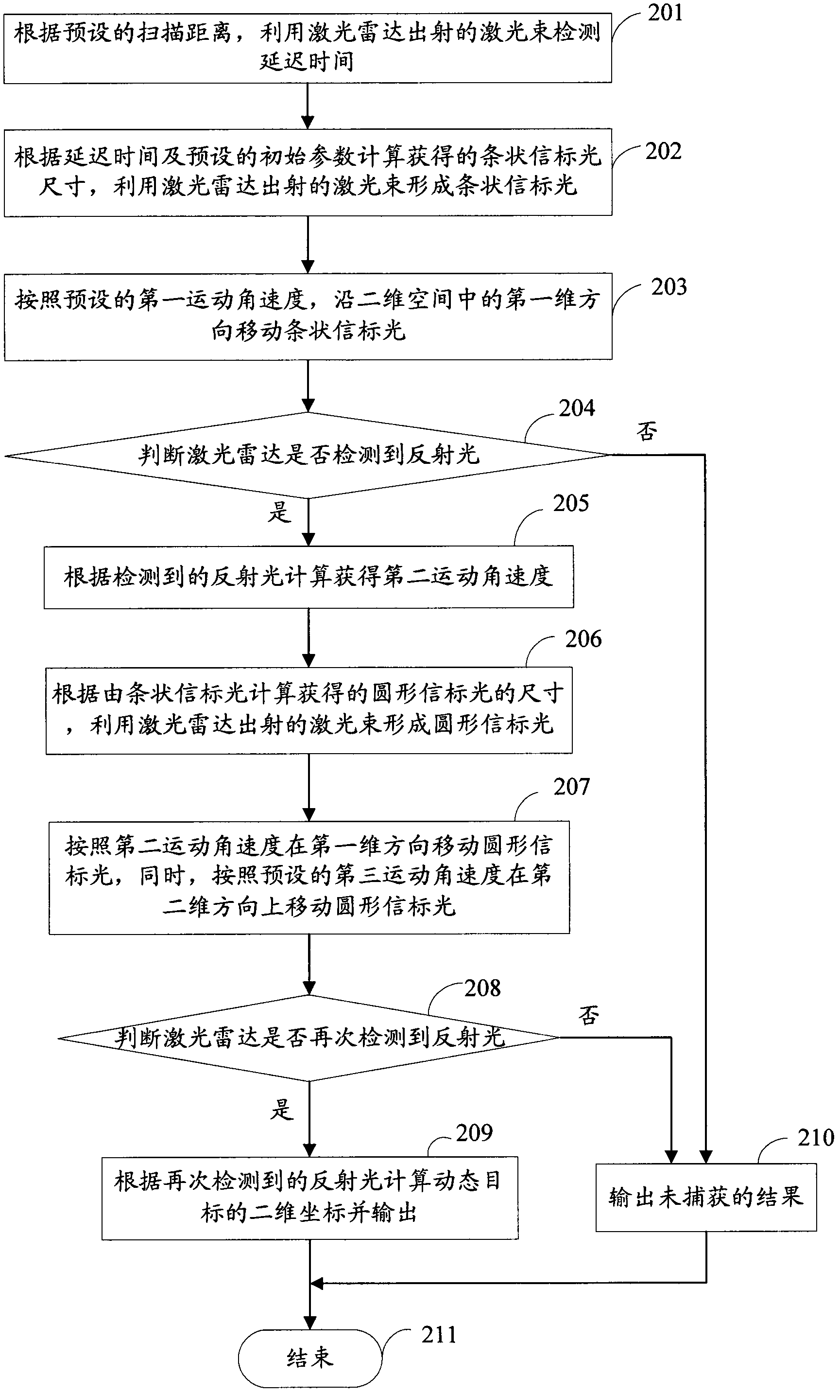
[0026] The metho...


PUM


Abstract

The invention provides a two-dimensional dynamic target capturing system, which comprises a laser, a laser beam expansion mirror, a light spot formation unit, an electrical control system and a photoelectric detection subsystem. The laser is used for producing a Gaussian laser beam under control of the electrical control system, and the Gaussian laser beam is transmitted to the light spot formation unit through the laser beam expansion mirror; the electrical control system is used for controlling the light spot formation unit and forming strip signaling light through the laser beam received by the light spot formation unit; the photoelectric detection subsystem is used for receiving reflected light when the strip signaling light is moved by the light spot formation unit, calculating a second angular speed of movement and transmitting the second angular speed of movement to the electrical control system; and the electric control system is also used for controlling the light spot formation unit and forming round signaling light through the laser beam received by the light spot formation unit from the laser beam expansion mirror. By adopting the scheme, the missing area of scanning can be reduced, and the capturing success rate can be increased.

Description

technical field [0001] The invention relates to laser radar technology, in particular to a system for two-dimensional capturing of dynamic targets. Background technique [0002] When using lidar technology to capture the dynamic target to be measured, in order to cover the entire capture field of view, the dynamic target must be tracked by scanning, and then the dynamic target is captured to obtain the position information of the dynamic target in the capture field of view. When capturing a dynamic target, the selection of the scanning method directly affects the success rate of capture; in the existing schemes for capturing a dynamic target, the circular spot is usually used as a beacon light for detecting the position of the dynamic target, according to The set scanning method uses the beacon light to track the dynamic target to be measured in two dimensions. [0003] figure 1 It is a schematic diagram of the beacon light movement track in the existing scanning mode; fi...

Claims


Application Information

Patent Timeline
Patent Type & Authority Applications(China)
IPC IPC(8): G01S17/66G01S7/48
Inventor 牛春晖刘明
Owner 北京国科环宇科技股份有限公司
Why Eureka
Try Eureka