screw pump

A technology for screw pumps and pump casings, applied to pumps, rotary piston pumps, rotary piston machines, etc., to achieve the effects of avoiding internal leakage, smooth changes, and low energy consumption

Active Publication Date: 2016-01-20
ZHEJIANG AOVITE HYDRAULIC MECHANICAL
View PDF8 Cites 0 Cited by
  • Summary
  • Abstract
  • Description
  • Claims
  • Application Information

AI Technical Summary

Problems solved by technology

[0006] In order to overcome the above-mentioned defects in the prior art, the present invention provides a screw pump with low noise, low vibration, and low energy consumption, which completely avoids the phenomenon of oil trapping in traditional gear pumps, thereby avoiding a series of problems caused by oil trapping ; And the friction between the gear side and the bearing is reduced, thereby reducing the frictional heat generation of the pump and effectively prolonging the service life of the pump

Method used


Image

  • screw pump
  • screw pump
  • screw pump

Examples


Embodiment

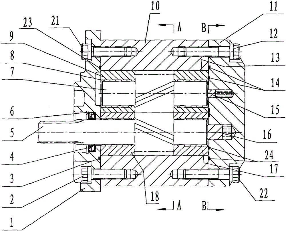
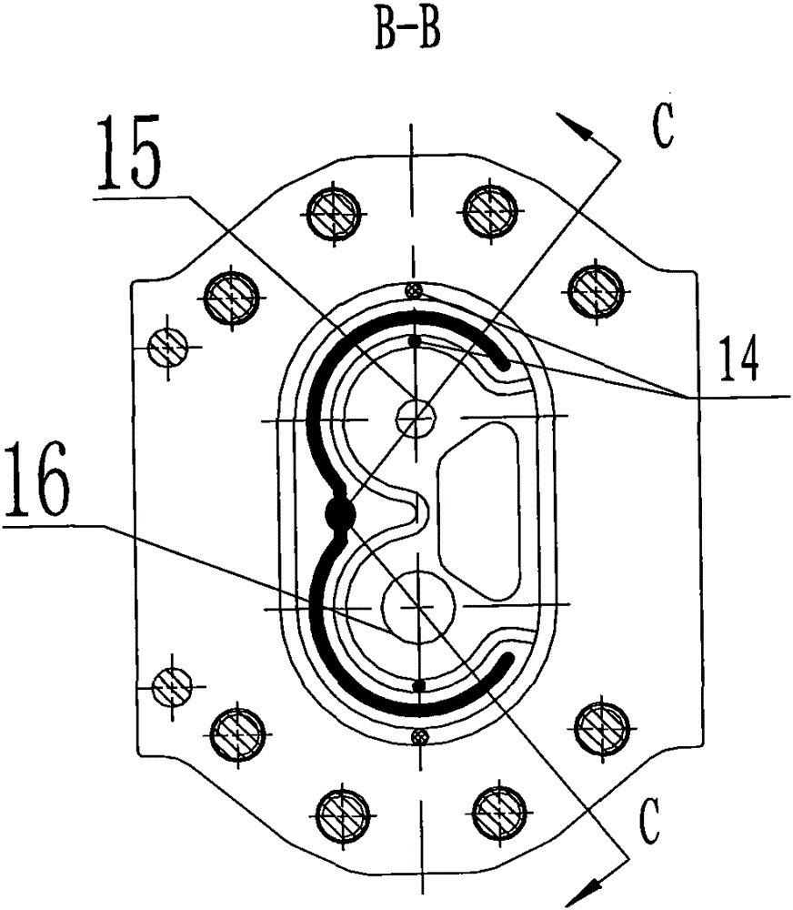
[0030] see figure 1 , figure 2 and image 3 , a screw pump, including a pump casing 10, an end cover 1 and an end cover 11 encapsulated on both sides of the pump casing 10, and a bearing 8 fixedly connected to the bearing housing 9, the bearing housing 13, the bearing housing 17 and the bearing housing 18, The driving helical gear 5 and the driven helical gear 7 that can be meshed in the bearing 8, the driving helical gear shaft ejector pin 16 arranged on the right end surface of the driving helical gear 5 and the driven helical gear arranged on the right end surface of the driven helical gear 7 Helical gear shaft jacking pin 15.

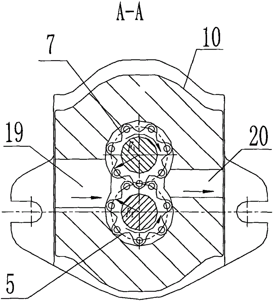
[0031] Such as figure 2 As shown, the left side of the driving helical gear 5 and the driven helical gear 7 is the oil suction port 19, and the right side is the oil pressure port 20, the oil suction port 19 is the low-pressure area, the oil pressure port 20 is the high-pressure area, and the low-pressure oil comes 19 enters, flows into the oi...


PUM


Abstract

The invention discloses a screw pump. The screw pump comprises a pump shell, an end cover packaged on the two ends of the pump shell, a bearing base arranged in the pump shell, a bearing fixedly connected to the bearing base, a driving screw gear arranged at the interior of the bearing and a driven screw gear. The screw pump is characterized in that the driving screw gear and the driven screw gear adopt spiral screw gear mechanisms, and a subsection circular arc which is tangential with the gear side is reserved at the tooth crest of the screw gear; the tooth crest and dedendum of the screw gear are in a circular arc, the tooth crest circular arc and the dedendum circular arc are mutually coincided and seamless, no bottom clearance exists, and the entrap phenomenon is not generated; and the sides of the driving screw gear and the driven screw gear are provided with oil storage tanks. The screw pump provided by the invention has the advantages of low noise, low vibration and low energy consumption, and can be used for completely avoiding the entrap phenomenon of a traditional gear wheel pump, reducing the friction of a gear and bearing, and prolonging the service life of a gear wheel pump.

Description

technical field [0001] The invention relates to hydraulic system power components, in particular to a screw pump. Background technique [0002] The disadvantages of the gear pump used in the hydraulic system of industrial machinery at present are that the flow output is pulsating, the noise is large, and the service life is short. [0003] The problem existing in the current gear pump is trapped oil. The phenomenon of trapped oil refers to a closed volume between two pairs of meshing teeth, which is called the trapped oil area, so that the oil remaining between the two pairs of teeth is trapped. in this enclosed volume. [0004] Due to the low compressibility of the oil, and the trapped oil area is a sealed volume, the trapped oil will be squeezed out from the gap of the mating surface of the parts, so that the gears and bearings are subjected to a large additional load. , reducing the life of the bearing, and at the same time generating power loss, it will also increase t...

Claims


Application Information

Patent Timeline
Patent Type & Authority Patents(China)
IPC IPC(8): F04C2/16
Inventor 翁海龙
Owner ZHEJIANG AOVITE HYDRAULIC MECHANICAL
Why Eureka
Try Eureka