
Oil tube testing plugging process and tube testing plugging device

A plugging and tubing technology, which is applied in the field of well control tools, can solve the problems of not reaching the plugging setting pressure, formation pollution, and increasing construction costs, so as to improve the plugging success rate, ensure the quality of sealing inspection, and improve the construction efficiency. efficiency effect

Inactive Publication Date: 2012-01-18
CHINA PETROLEUM & CHEM CORP +1
View PDF3 Cites 4 Cited by
  • Summary
  • Abstract
  • Description
  • Claims
  • Application Information

AI Technical Summary

Problems solved by technology

After setting, it is not possible to unseat and change the setting position. It can only be unsealed with a special unsealing tool after the oil pipe is lifted out during the operation; it cannot be set and unsealed multiple times to realize the inspection function
Since the oil pipe plugging process has no pipe inspection function and lacks pipe inspection procedures, when there is a leak in the pipe string or the oil pipe hanger is damaged, the location of the leak cannot be judged, and the plugging can only be carried out many times blindly, which seriously affects the The success rate of oil pipe plugging increases the construction cost; 2. The current plug setting method is single, and the plug can only be set by the pressure in the tubing. When encountering a well with serious stratum crossing, the tubing pressure cannot reach the plug The setting pressure is too high, so that the tubing cannot be blocked, and the snubbing operation cannot be carried out, and the well can only be killed, which leads to formation pollution and affects the production of the oil well

Method used


Image

  • Oil tube testing plugging process and tube testing plugging device
  • Oil tube testing plugging process and tube testing plugging device
  • Oil tube testing plugging process and tube testing plugging device

Examples


Embodiment Construction

[0015] Below in conjunction with accompanying drawing, the present invention is described in further detail:

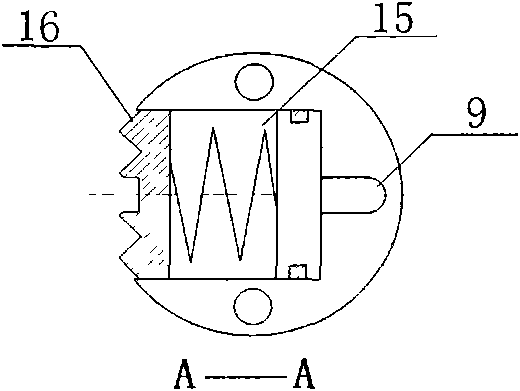
[0016] A kind of plugging process of oil pipe test tube is to connect the test tube plug in the oil pipe in the well with the ground pressure test pump through the capillary tube, and use the capillary to connect the internal pressure transmission channel of the test tube plug to verify the leak point of the oil pipe first, and then plug the oil pipe . To verify the leak point of the oil pipe, use the pipe inspection plug to plug the oil pipe without losing hands at different inspection positions, and judge the leak point position of the oil pipe by observing the overflow of the overflow port of the wellhead blowout preventer when the oil pipe is blocked. Plugging the oil pipe is to lower the test tube stopper to the pre-blocking position of the oil pipe, connect the internal pressure transmission channel of the test tube stopper through the capillary, and block the o...


PUM


Abstract

The invention discloses an oil tube testing plugging process and a tube testing plugging device, applicable to inspection of leak sources of an oil tube and plugging of the oil tube in oil-water well operation under pressure in the petroleum industry, wherein tubular column plugging success rate is improved, and production safety is ensured. The tube testing plugging process disclosed by the invention is as follows: a tube testing plugging device in the oil tube in a well is connected with a ground pressure testing pump by virtue of a capillary tube, the capillary tube is communicated with an internal pressure transfer channel of the tube testing plugging device, firstly the leak sources of the oil tube are tested, and then the oil tube is plugged, thus integration of tube testing and plugging is realized. The tube testing plugging device disclosed by the invention comprises a rubber barrel part and an anchoring part, the plugging device is internally provided with an internal pressure transfer channel and a releasing part, the anchoring part is welded between the releasing part and the rubber barrel part, and the internal pressure transfer channel is used for transferring pressure, thus integration of throwing, fishing and suppressing is realized. By virtue of an internal pressure transfer channel set packer of the tube testing plugging device, cross strata influence is not produced, and plugging success rate is improved.

Description

technical field [0001] The invention relates to a well control tool for downhole operations in the petroleum industry, in particular to a technique for inspecting oil pipe plugging and a plugging device for inspecting oil pipes under pressure, which is suitable for inspecting oil pipe leakage points and sealing oil pipes during oil-water well pressure operations, and improving the success rate of pipe string plugging , to ensure safe production. Background technique [0002] The existing plugging process of oil and water wells with pressure operation is to deliver the plug to the predetermined depth through the salvage vehicle, and to block the oil pipe through the positive pressure setting plug of the tubing, which has the following disadvantages: 1. The plug currently used is mainly composed It consists of main components such as tiles, rubber cartridges, snap rings, and shear nails. Its principle is to cut the setting shear nails through the pressure in the oil pipe, spre...

Claims


Application Information

Patent Timeline
Patent Type & Authority Applications(China)
IPC IPC(8): E21B33/127E21B47/10
Inventor 魏斌高广启罗文莉金鑫宋辉辉付增程正全李新华张方圆
Owner CHINA PETROLEUM & CHEM CORP
Learn More