Eureka AIR delivers breakthrough ideas for toughest innovation challenges, trusted by R&D personnel around the world.

Hoisting in-place method for allowing large equipment to pass through ultrahigh hole

A large-scale equipment and ultra-high technology, which is applied in the field of hoisting large-scale equipment through ultra-high holes, can solve the problems of long hoisting time, slow hoisting speed, and low secondary recovery rate of materials, and achieve short hoisting time, convenient operation, The effect of simple structure

Active Publication Date: 2013-01-09
中建六局第一建设有限公司
View PDF6 Cites 0 Cited by
  • Summary
  • Abstract
  • Description
  • Claims
  • Application Information

AI Technical Summary

Problems solved by technology

[0002] At present, for the hoisting of high-rise and super-high-rise large-scale equipment, most of them use gantry bridges to hoist equipment into place. The main disadvantages of this method of using gantry bridges to hoist equipment into place are: ①The structure of the hoisting equipment is complex, It is difficult to erect; ②The structure of the lifting equipment has many power points, requiring more investment in mechanical equipment and human resources; ③The erection of the main hoisting structure of the equipment requires a large amount of materials, and the secondary recovery rate of materials is low; ④The hoisted equipment is vertical And the hoisting speed of horizontal transportation is slow, and the overall hoisting time is longer

Method used


Image

  • Hoisting in-place method for allowing large equipment to pass through ultrahigh hole
  • Hoisting in-place method for allowing large equipment to pass through ultrahigh hole
  • Hoisting in-place method for allowing large equipment to pass through ultrahigh hole

Examples


Embodiment Construction

[0023] In order to further understand the invention content, characteristics and effects of the present invention, the following examples are given, and detailed descriptions are as follows in conjunction with the accompanying drawings:

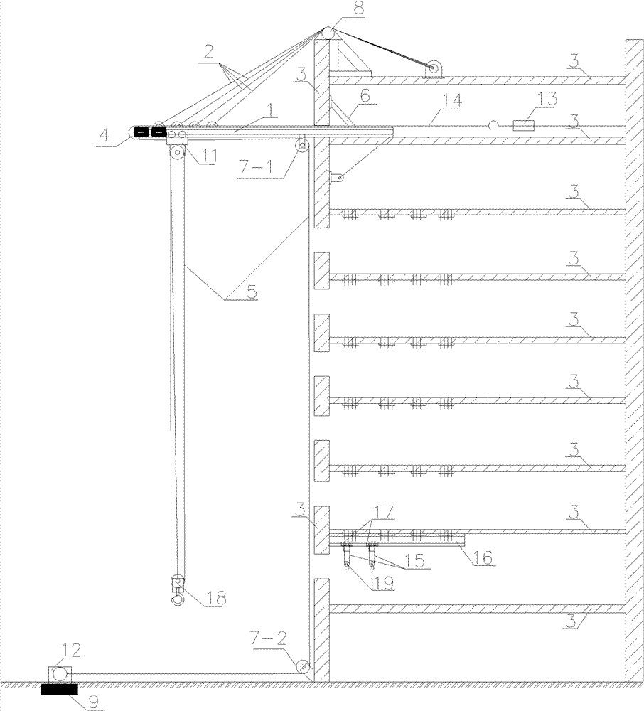
[0024] A method for hoisting large-scale equipment into place through a super-high hole, which is characterized in that the hoisting equipment is hoisted by a high-altitude monorail combined cantilever crane.

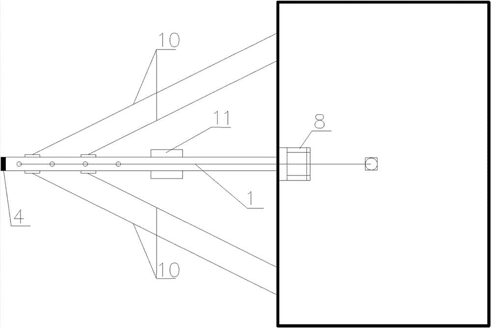
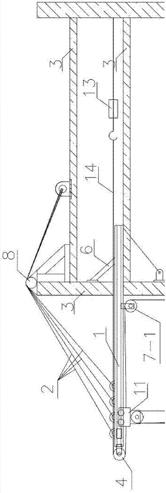
[0025] see Figure 1 to Figure 6 , the high-altitude monorail combined cantilever crane includes a main hanger located on the outside of the building structure 3 and an auxiliary hanger located on the inside of the building structure;

[0026] The main hanger includes a cantilever 1 affixed to the top of the building structure 3, and the cantilever 1 is provided with a stabilizing device; the cantilever is provided with a monorail along the length direction, and the cantilever monorail is provided with a main hanger monorail trolley 11...


PUM


Abstract

The invention discloses a hoisting in-place method for allowing large equipment to pass through an ultrahigh hole. Hoisting equipment of a high-altitude monorail combined cantilever crane is adopted in the method, and the high-altitude monorail combined cantilever crane comprises a main crane positioned at the outer side of a building structure and a secondary crane positioned at the inner side of the building structure. The method adopting the hoisting equipment of the high-altitude monorail combined cantilever crane comprises the following steps of: (1) hoisting the equipment to a reserved hole by using the main crane, and effectively butting the equipment and the edge of the reserved hole: 1) positively starting a winch, hoisting the equipment above the reserved hole, and braking the winch; 2) loosening a balance chain block, lowering the equipment at the same time of horizontal movement, and gradually moving the equipment to the reserved hole; 3) repeating the steps 1) and 2), starting and stopping the winch and loosening and tightening the position of balance chain block adjusting equipment till the equipment body is effectively butted with the edge of the reserved hole; and (2) drawing the equipment to the interior of the building structure by using the secondary crane, loosening a hook of the main crane, and hoisting the equipment in place by using the secondary crane. The method is convenient for operation and short in hoisting time.

Description

technical field [0001] The invention relates to a method for hoisting and placing large equipment, in particular to a method for hoisting and placing large equipment through a superhigh hole. Background technique [0002] At present, for the hoisting of high-rise and super-high-rise large-scale equipment, most of them use gantry bridges to hoist equipment into place. The main disadvantages of this method of using gantry bridges to hoist equipment into place are: ①The structure of the hoisting equipment is complex, It is difficult to erect; ②The structure of the lifting equipment has many power points, requiring more investment in mechanical equipment and human resources; ③The erection of the main hoisting structure of the equipment requires a large amount of materials, and the secondary recovery rate of materials is low; ④The hoisted equipment is vertical And the hoisting speed of horizontal transportation is slow, and the overall hoisting time is longer. Contents of the i...

Claims


Application Information

Patent Timeline
Patent Type & Authority Patents(China)
IPC IPC(8): B66C19/00
Inventor 李永红生振杰王存贵倪惠平罗旭东王建旭
Owner 中建六局第一建设有限公司
Why Eureka
Eureka Blog
Learn More