Multiresonance antenna

An antenna and resonance technology, which is applied to the antenna field of small radio equipment, can solve the problems of increasing equipment production costs and requiring space, and achieves the effect of not causing production costs to rise.

Inactive Publication Date: 2012-01-11
PULSE FINLAND
View PDF1 Cites 2 Cited by
  • Summary
  • Abstract
  • Description
  • Claims
  • Application Information

AI Technical Summary

Problems solved by technology

However, the extra components require space and increase the production cost of the device

Method used


Image

  • Multiresonance antenna
  • Multiresonance antenna
  • Multiresonance antenna

Examples


Embodiment Construction

[0020] Figure 1 has already been described in conjunction with the description of the prior art.

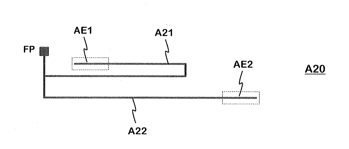
[0021] Figure 2a -c shows possible radiator forms as an introduction to the invention. In all examples, the radiator comprises two arms, seen from the feed point, and the profile of the radiator forms an elongated region, which in turn has a longitudinal direction and a transverse direction. exist Figure 2a In , the feed point FP of the radiator is located at one end of the area formed by the outline of the radiator, at a corner of the area. Starting from the feed point FP, the arms of the radiator first have a relatively short lateral shared portion. In the first arm A21 there is a longitudinal first part, a U-shaped bend and a longitudinal tail after said shared part. The tail extends relatively close to the start of the arm and the feed point FP. In the second arm A22, as a continuation of said shared part, there is a first transverse part and a second longitudinal part, ...


PUM


Abstract

An antenna especially intended for small-sized radio devices, which antenna has more than one resonance for shaping an operating band. The radiating element (320) of the antenna has, viewed from its feed point (FP), a first (321) and a second (322) arm with nearly equal electric lengths. The tail ends of the arms are located on different sides of the area confined by the outline of the radiator and point to opposite directions away from each other for exciting a double resonance in the antenna. The second arm has at least one extension towards the tail portion of the first arm. Also an operating band in the range of 900 MHz can be widened by means of the extra resonance without an extra element. The solution is simple and hardly causes rise in the production costs.

Description

technical field [0001] The invention relates to an antenna, especially intended for small radio equipment, having more than one resonance in order to shape the operating band. Background technique [0002] In a small radio device such as a mobile phone, the antenna to be placed inside the device is usually of type IFA (inverted F antenna) or ILA type (inverted L antenna). In both cases, the antenna includes a ground plane and a radiating plane parallel to it for coupling to the antenna port of the device. In an IFA, the radiator is also shorted from its specific point to the ground plane to arrange matching. If the radiator is sheet-like, the names PIFA (Planar IFA) and PILA (Planar ILA) are used. [0003] Available space is a particularly critical factor in antenna design, especially when air is used as an insulator between the radiator and the ground plane, which is advantageous from an antenna efficiency standpoint. The distance between the radiator and the ground plan...

Claims


Application Information

Patent Timeline
Patent Type & Authority Applications(China)
IPC IPC(8): H01Q5/01H01Q1/24H01Q9/04H01Q9/42H01Q5/10
CPCH01Q9/30H01Q21/28H01Q1/243H01Q9/42H01Q1/38H01Q5/0062H01Q5/378H01Q5/10H01Q9/0407H01Q23/00H01Q9/0414H01Q9/0421H01Q5/335H01Q5/371H01Q5/40
Inventor M.N.伊斯拉姆
Owner PULSE FINLAND
Why Eureka
Try Eureka