
Method and device for acquiring routing information of electro-optical multi-layer network

A multi-layer network and acquisition method technology, which is applied in the field of automatic switching optical network, can solve the problems of wrong calculation results, failure to achieve the optimum, and inability to accurately describe the electro-optic multi-layer network, so as to achieve the goal of perfecting the information model and improving the accuracy Effect

Inactive Publication Date: 2012-01-11
ZTE CORP
View PDF3 Cites 9 Cited by
  • Summary
  • Abstract
  • Description
  • Claims
  • Application Information

AI Technical Summary

Problems solved by technology

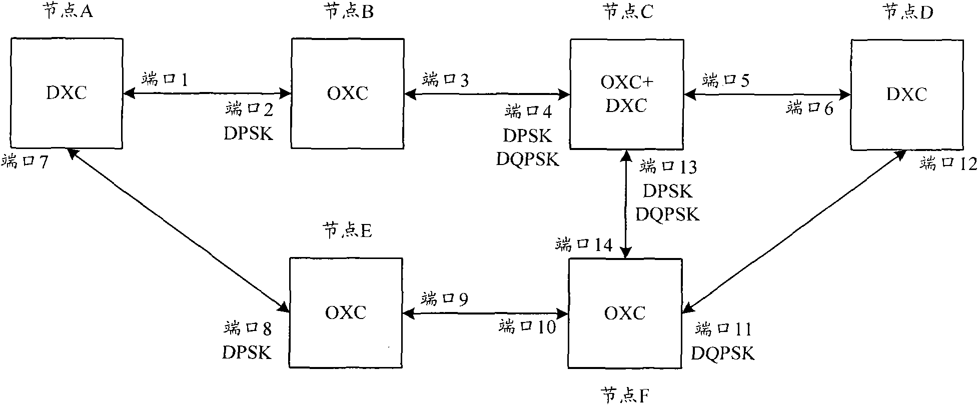
However, due to the particularity of the electro-optical multi-layer network, for example, when establishing a connection, the electrical layer connection needs to pass through an optical layer network, then the edge links on both sides of the optical layer network are used for adaptation between optical nodes The optical transmitter / receiver associated with the link needs to have the same signal processing capability; at the same time, if the wavelength of the two-way connection is required to be the same, then the optical transmitters on both sides need to be able to tune the same wavelength, but this information is currently There are no MLN and WSON information models
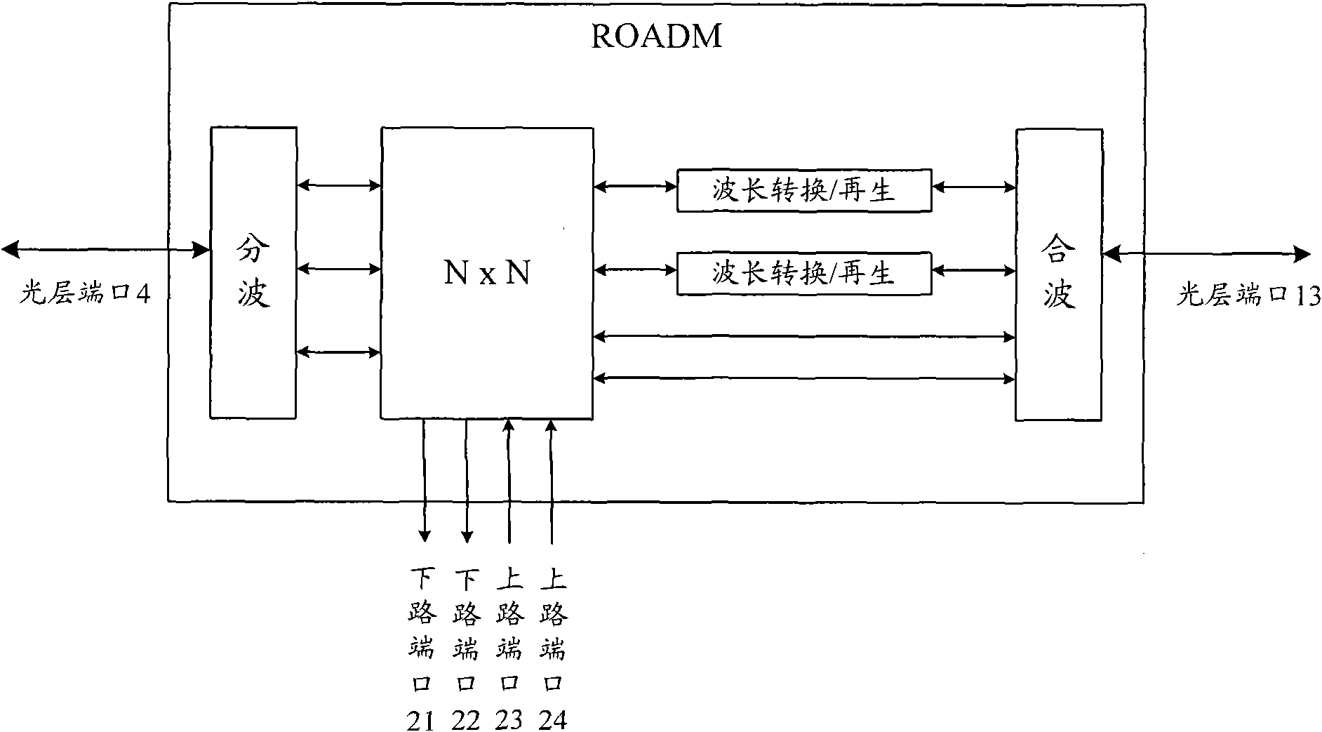
from right figure 1 and figure 2 From an analysis point of view, the above routing information still cannot accurately describe the electro-optical multi-layer network, so that the calculation results may be wrong or not optimal due to the lack of information during path calculation.

Method used


Image

  • Method and device for acquiring routing information of electro-optical multi-layer network
  • Method and device for acquiring routing information of electro-optical multi-layer network
  • Method and device for acquiring routing information of electro-optical multi-layer network

Examples


Embodiment Construction

[0074] The devices involved in the present invention, the following devices have been described in detail in relevant standards or professional documents, here is only a brief description:

[0075] The optical transmitter is used to encode the signal sent by the electrical multiplexing equipment, and then perform electrical-optical conversion through modulation and couple it into the optical fiber;

[0076] The optical receiver is used to convert the wavelength received from the optical fiber through demodulation to photoelectric conversion, and then restore the signal through decoding and send it to the electrical multiplexing device;

[0077] OXC is used for wavelength exchange, for example, ROADM can be regarded as an OXC device;

[0078] DXC is used to switch electrical layer signals between different link ports. For example, the crossover board in SDH equipment is an electrical switching matrix;

[0079] Fiber link, used to connect physical fibers between two nodes;

[...


PUM


Abstract

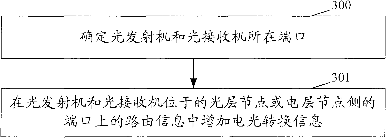
The invention discloses a method and a device for acquiring the routing information of an electro-optical multi-layer network. The method comprises the following steps of: determining ports in which an optical transmitter and an optical receiver are positioned; and adding electro-optical conversion information into the routing information on the ports, in which the optical transmitter and the optical receiver are positioned, on an optical layer node side or an electrical layer node side, wherein the electro-optical conversion information comprises, but not limited to, wavelength tuning capacity and signal processing capacity. The invention has the advantages that: by expanding information models of the conventional multi-layer network (MLN) and a wavelength switched optical network (WSON), the routing information which comprises the electro-optical conversion information is more accurately described, and the information model of the electro-optical multi-layer network is perfected, so the accuracy of path calculation is improved, and the path calculation is optimized.

Description

technical field [0001] The invention relates to Automatically Switched Optical Network (ASON, Automatically Switched Optical Network) technology, in particular to a method and device for obtaining electro-optic conversion information in routing information of an electro-optic multi-layer network. Background technique [0002] In traditional communication networks, dedicated service platforms are built for each service. In this way, service resources are difficult to integrate and share, and operators must maintain multiple service platforms at the same time, resulting in double waste of network construction costs and maintenance resources. [0003] Supporting the high-reliability network system is the optical fiber-based transmission network. With the rapid development of data services, new modes such as broadband multi-service transmission and end-to-end bandwidth provision continue to emerge. Traditional Synchronous Digital Hierarchy (SDH, Synchronous Digital Hierarchy) te...

Claims


Application Information

Patent Timeline
Patent Type & Authority Applications(China)
IPC IPC(8): H04L12/56H04Q11/00H04L45/02
CPCH04J14/0227H04L45/02H04J14/0212H04L12/56
Inventor 谢刚
Owner ZTE CORP
Learn More