
Combustion gas generator of biomass

A biomass gas and generator technology, which is used in the manufacture of combustible gas, fixed bed gasification, petroleum industry, etc., can solve the problems of limiting the wide application of biomass gasification devices, reducing equipment utilization, and reducing production efficiency. Improve utilization and production efficiency, reduce labor intensity, and avoid waste

Inactive Publication Date: 2012-01-11
JINAN BODE ENERGY TECH
View PDF4 Cites 6 Cited by
  • Summary
  • Abstract
  • Description
  • Claims
  • Application Information

AI Technical Summary

Problems solved by technology

[0003] However, the current biomass gasification device needs to regularly remove the ash at the bottom of the furnace body to ensure the normal operation of the gasification device, which makes the equipment unable to operate continuously and efficiently, reducing the utilization rate of the equipment, and reducing production efficiency. The efficiency is reduced, which greatly wastes resources. At the same time, the equipment cannot be applied to industries such as power generation and heating that require continuous operation, which limits the wide application of biomass gasification devices.

Method used


Image

  • Combustion gas generator of biomass
  • Combustion gas generator of biomass
  • Combustion gas generator of biomass

Examples


Embodiment Construction

[0020] In order to clearly illustrate the technical features of this solution, the present invention will be described in detail below through specific implementation modes and in conjunction with the accompanying drawings.

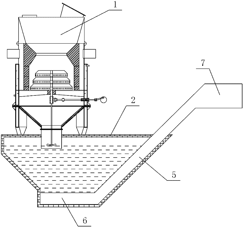
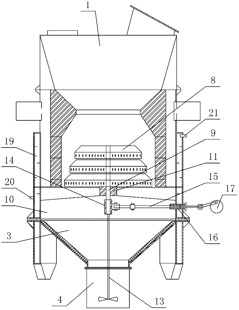
[0021] Such as Figure 1~6 Shown, the present invention comprises gasification furnace 1, is provided with the airtight deashing pool 2 that an inside is filled with water in the bottom of gasification furnace 1, is located at the lower furnace body 3 bottom of gasification furnace 1 and stretches into In the ash removal tank 2, an ash removal device 5 is arranged in the ash removal tank 2. The ash suction end 6 of the ash removal device 5 extends to the bottom of the ash removal tank 2, and the ash output end 7 extends to the outside of the ash removal tank 2.

[0022] The grate 8 of the gasification furnace 1 is composed of several layers of sub-grates arranged sequentially from top to bottom, and each sub-grate is fixedly connected with a rotating shaf...


PUM


Abstract

The invention relates to a combustion gas generation device, in particular to a combustion gas generator of biomass, comprising a vapourizing furnace, wherein, an enclosed dusting pool filled with water is arranged below the vapourizing furnace, an ash inlet arranged at the bottom of the lower furnace body of the vapourizing furnace is inserted to the dusting pool, the dusting pool is provided with a dusting unit, the ash-suction end of the dusting unit is inserted in the bottom of the dusting pool, and the ash-discharge end extends to the outside of the dusting pool. he invention has the advantages of simple structure and reasonable design, can guarantee the normal operation of the device continuously, efficiently and stability, improves the utilization rate and production efficiency of the device, and avoids the waste of resource.

Description

Technical field: [0001] The invention relates to a gas generating device, in particular to a biomass gas generator. Background technique: [0002] At present, the biomass pyrolysis and gasification technologies used in my country mainly include three process forms: fixed bed, fluidized bed and direct carbonization pyrolysis. The fixed bed gasifier process, especially the downdraft fixed bed, generally uses air as the gasification agent, which is characterized by simple equipment structure, easy operation, pyrolysis and gasification of various biomass materials, and low investment. It has been widely used in our country. [0003] However, the current biomass gasification device needs to regularly remove the ash at the bottom of the furnace body to ensure the normal operation of the gasification device, which makes the equipment unable to operate continuously and efficiently, reducing the utilization rate of the equipment and reducing production capacity. The efficiency is r...

Claims


Application Information

Patent Timeline
Patent Type & Authority Applications(China)
IPC IPC(8): C10J3/34C10J3/42C10J3/76
Inventor 薛爱军辛思学岳现文陈盛勇
Owner JINAN BODE ENERGY TECH
Learn More