Method for producing pneumatic tire and pneumatic tire

A technology for pneumatic tires and green tires, which can be used in pneumatic tires, special tires, tire parts, etc., and can solve problems such as bad appearance and impression

Inactive Publication Date: 2012-01-11
SUMITOMO RUBBER IND LTD
View PDF14 Cites 1 Cited by
  • Summary
  • Abstract
  • Description
  • Claims
  • Application Information

AI Technical Summary

Problems solved by technology

This phenomenon causes the problem that the small speckle pattern formed on the inner side of the tire gives a bad appearance impression to the user
Therefore, there is a problem that when the vulcanized tire is released from the mold, the inner liner adhered to the air bag is taken away from the air bag side, causing an air-in phenomenon between the inner liner and the insulation layer or the carcass

Method used


Image

  • Method for producing pneumatic tire and pneumatic tire
  • Method for producing pneumatic tire and pneumatic tire
  • Method for producing pneumatic tire and pneumatic tire

Examples


specific Embodiment approach 1

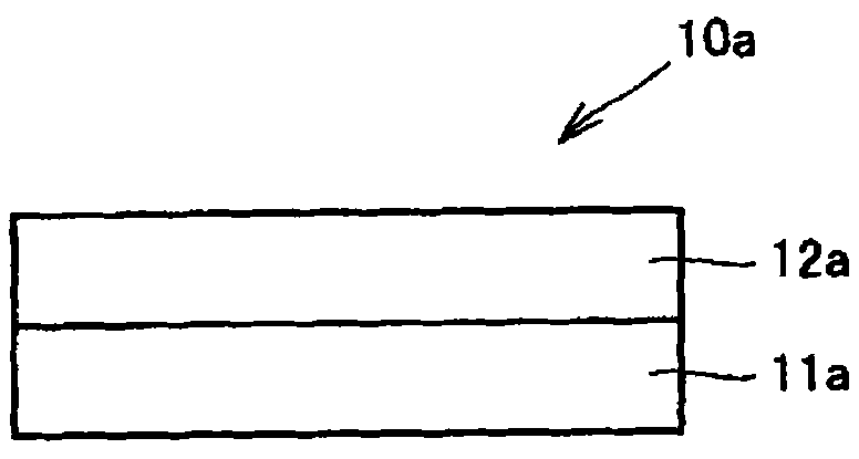
[0063] like figure 2 As shown, in one embodiment of the invention, a polymeric laminate 10a is composed of a first layer 11a and a second A-layer 12a.

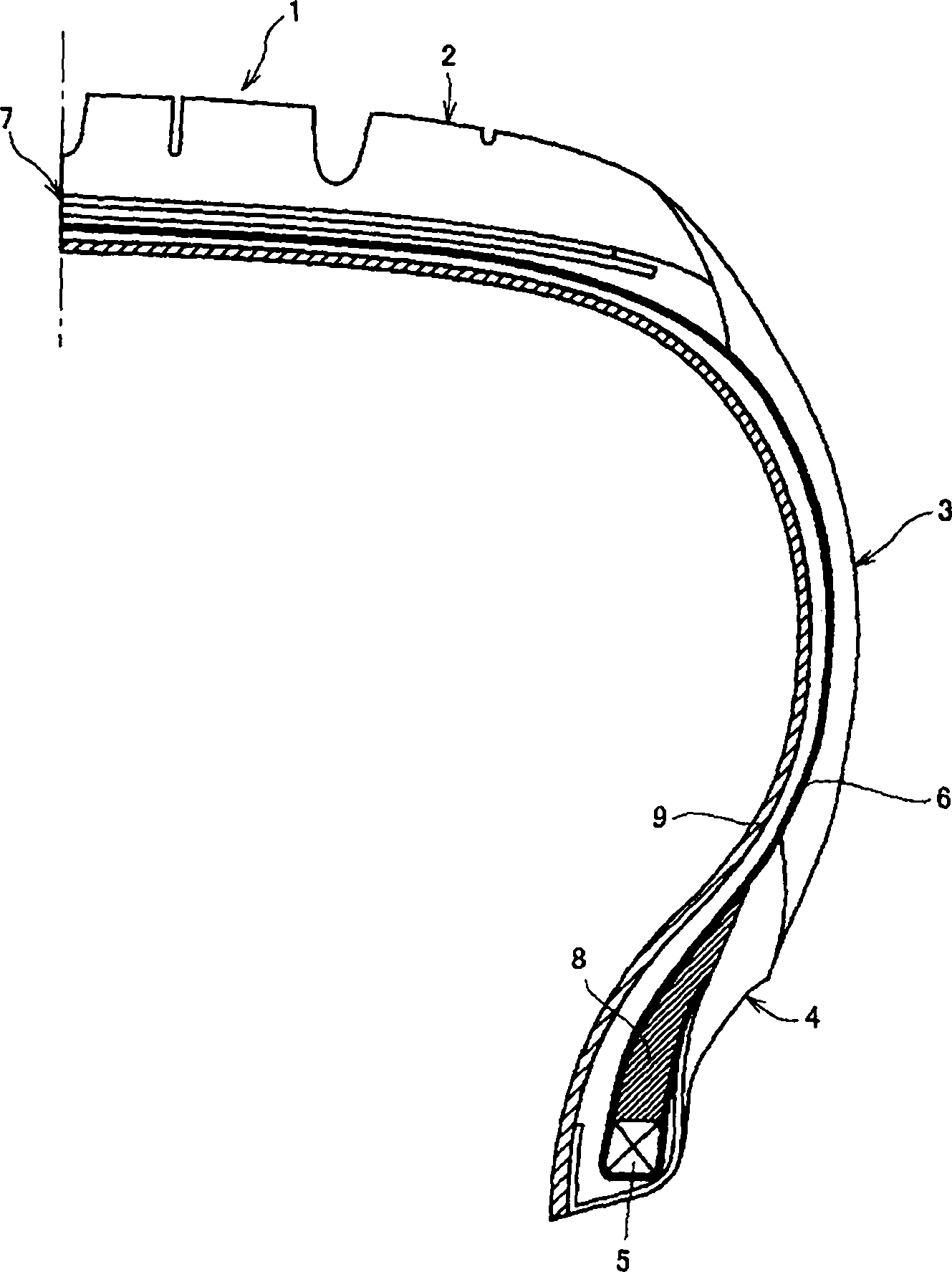
[0064] see figure 1 , when the polymer laminate 10a is used as the airtight layer 9 of the pneumatic tire 1, if the surface where the first layer 11a is located is set toward the radially innermost side of the tire, and the surface where the second A layer 12a is located is set toward the radially outer side In order to reach the carcass 6, the second A layer 12a and the carcass 6 can be vulcanized into bonds in the tire vulcanization step. Therefore, since the inner liner 9 is satisfactorily bonded to the rubber layer of the carcass 6, the resulting pneumatic tire 1 can have excellent air permeability resistance and durability.

specific Embodiment approach 2

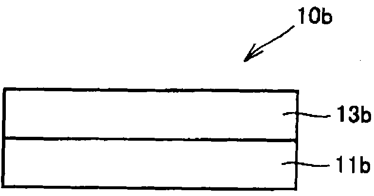
[0065] like image 3 As shown, in one embodiment of the invention, the polymer laminate 10b is composed of a first layer 11b and a second B layer 13b.

[0066] see figure 1 , when the polymer laminate 10b is used as the airtight layer 9 of the pneumatic tire 1, if the surface where the first layer 11a is located is arranged toward the innermost side in the tire radial direction, and the surface where the second B layer 13b is located is arranged toward the radially outer side In order to reach the carcass 6, the second B layer 13b and the carcass 6 can be vulcanized into bonds in the tire vulcanization step. Therefore, since the inner liner 9 is satisfactorily bonded to the rubber layer of the carcass 6, the resulting pneumatic tire 1 can have excellent air permeability resistance and durability.

specific Embodiment approach 3

[0067] like Figure 4 As shown, in one embodiment of the present invention, a polymer laminate 10c is laminated from a first layer 11c, a second A layer 12c, and a second B layer 13c in the order described above.

[0068] see figure 1 , when the polymer laminate 10c is used as the airtight layer 9 of the pneumatic tire 1, if the surface where the first layer 11c is located is set toward the innermost side in the tire radial direction, and the surface where the second B layer 13c is located is set toward the radially outer side In order to reach the carcass 6, the second B layer 13c and the carcass 6 can be vulcanized into bonds in the tire vulcanization step. Therefore, since the inner liner 9 is satisfactorily bonded to the rubber layer of the carcass 6, the resulting pneumatic tire 1 can have excellent air permeability resistance and durability.


PUM

PropertyMeasurementUnit
degree of polymerizationaaaaaaaaaa

Abstract

A method for producing a pneumatic tire in which an air-in phenomenon between an inner liner and a carcass is avoided by preventing adhesion of the inner liner to a bladder includes the following steps. A green tire using, as an inner liner, a polymer laminate including a first layer (11a) having a thickness of 0.05 mm to 0.6 mm made of a styrene-isobutylene-styrene triblock copolymer, and a second layer (12a) composed of at least one of a second A layer made of a styrene-isoprene-styrene triblock copolymer and a second B layer made of a styrene-isobutylene diblock copolymer, the second layer having a thickness of 0.01 mm to 0.3 mm, is prepared. The green tire is mounted in a mold for vulcanization with pressurization by the bladder to obtain a vulcanized tire. The vulcanized tire is cooled at 50 to 120 DEG C for 10 to 300 seconds.

Description

[0001] This non-provisional application is based on No. 2010-147934 filed with the Japan Patent Office on June 29, 2010, No. 2010-165958 filed with the Japan Patent Office on July 23, 2010, and No. Japanese Patent Application No. 2010-236045 filed, the entire contents of which are hereby incorporated by reference. technical field [0002] The present invention relates to a method for producing a pneumatic tire, and more particularly, to a method for producing a pneumatic tire having a polymer laminate serving as an inner liner; Production of pneumatic tires. Background technique [0003] Recently, due to strong social demand for fuel-efficient automobiles, tire weight reduction has been attempted. In the tire member, there have also been attempts to implement weight reduction of the inner liner, which is provided on the inner side in the tire radial direction and has the function of improving by reducing the amount of air leakage (air permeation amount) from the inside to t...

Claims


Application Information

Patent Timeline
Patent Type & Authority Applications(China)
IPC IPC(8): B60C1/00C08L53/02B32B27/08B32B27/30
CPCB32B25/16B32B2274/00B32B25/08B29D30/0681B29D2030/0682B60C2005/145B32B2605/08B60C5/14B60C1/0008B32B7/12B32B27/302B32B2307/54B32B2307/712B32B2307/7242B32B2307/732Y10T152/10495B29C35/02B29D30/08C08F297/04C08F297/08
Inventor 杉本睦树
Owner SUMITOMO RUBBER IND LTD
Why Eureka
Try Eureka