Automatic tape-laying forming method for composite material with hollowed-out structure
A composite material and hollow structure technology, which is applied in the field of automatic tape laying and forming of composite materials, can solve the problems of restricting the shape of laying products, increasing the workload of cutting knives, and wrinkles on the surface of prepreg tape, so as to reduce post-processing work Quantity, improve molding efficiency, reduce the effect of product quality
- Summary
- Abstract
- Description
- Claims
- Application Information
AI Technical Summary
Problems solved by technology
Method used
Image
Examples
specific Embodiment approach 1
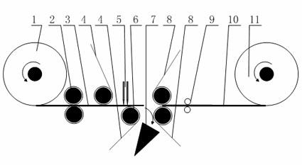
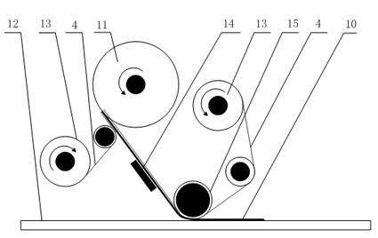
[0029] Specific implementation mode one: combine figure 1 , 2 , 3, 4, 5, 6, 7, and 8 describe this embodiment. When forming a composite material with a hollow structure, the shape of the prepreg tape is first designed according to the shape and size to be formed, the width of the prepreg tape and the direction of the layup, and then the trajectory of the double cutter 5 is obtained. use as figure 1 The pre-cutting unit shown, performs pre-cutting of prepreg tape. The prepreg tape 3 to be cut is led out from the unwinding roll 1 by the guide roller 2, and after the backing paper 4 is peeled off, the prepreg tape 3 is cut into a predetermined shape by double cutters 5. In order to ensure efficiency and realize continuous production, the cutting depth of the double cutter 5 needs to be strictly controlled, so that the backing paper can not be cut while cutting the prepreg. After the prepreg is cut, add a new backing paper 8 (one layer can be replaced by a film), and then comp...
specific Embodiment approach 2
[0035] Specific implementation mode two: combination Figure 5 , 6 , 7 describe this embodiment. Compared with the first embodiment, the forming principle of this embodiment is the same, but there are differences in the pre-cutting and laying methods of the prepreg tape, that is, the winding method of the single-layer backing paper. Such as Figure 5 As shown, after the prepreg tape is pre-cut, a layer of new backing paper 8 is added below, and a special backing film 16 is used to replace the top. Backing paper. When laying the prepreg tape, if Figure 6 As shown, a paving head paper motor 13 can be omitted, and its schematic diagram is as follows Figure 7 .
specific Embodiment approach 3
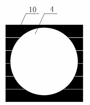
[0036] Specific implementation mode three: combination Figure 8 , 9 , 10, and 11 describe this embodiment. When it comes to the laying and molding of composite materials with a large number of grid-like structures, the automatic tape-laying of -45° ply grid-like materials is taken as an example. The pre-cut prepreg tape shape should be designed in advance considering the mesh size and prepreg tape width. Pre-cut prepreg tape into Figure 9 After laying the shape shown, the molding effect is as follows Figure 9 , where the arrow points to the laying direction of the prepreg tape, black represents the prepreg tape, and white represents the formed grid shape. If the prepreg tape is precut into Figure 10The shape shown, the molding effect is as follows Figure 11 shown.
PUM
 Abstract
Description
Claims
Application Information
 - R&D
- Intellectual Property
- Life Sciences
- Materials
- Tech Scout
- Unparalleled Data Quality
- Higher Quality Content
- 60% Fewer Hallucinations
Browse by: Latest US Patents, China's latest patents, Technical Efficacy Thesaurus, Application Domain, Technology Topic, Popular Technical Reports.
© 2025 PatSnap. All rights reserved.Legal|Privacy policy|Modern Slavery Act Transparency Statement|Sitemap|About US| Contact US: help@patsnap.com


