Stud welding gun

A technology of stud welding and torch shell, applied in the direction of electrode characteristics, welding equipment, arc welding equipment, etc., can solve the problems of stud inclination, stud not vertical, etc., and achieve easy welding operation, compact structure, and accurate axis positioning Effect

Active Publication Date: 2012-11-21
SUZHOU POWER SUPPLY OF JIANGSU ELECTRIC POWER
View PDF6 Cites 0 Cited by
  • Summary
  • Abstract
  • Description
  • Claims
  • Application Information

AI Technical Summary

Problems solved by technology

[0005] When welding long studs with traditional stud welding guns, the studs tend to be tilted, and the studs are not perpendicular to the workpiece

Method used


Image

  • Stud welding gun
  • Stud welding gun

Examples


Embodiment Construction

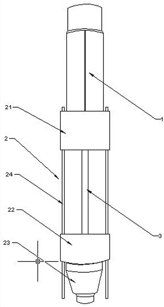
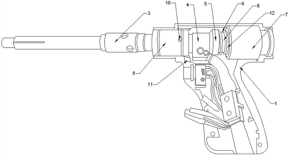
[0017] Attached below Figure 1-2 One is to describe the preferred embodiments of the present invention in detail, so that the advantages and features of the present invention can be more easily understood by those skilled in the art, so as to define the protection scope of the present invention more clearly.

[0018] A kind of stud welding torch, it comprises gun case 1 and the end cover group 2 that is used for positioning stud that is arranged on the gun case 1, and described end cover group 2 comprises two aluminum sleeves and positioning ring, and the aluminum sleeve at the rear end 21 is clamped with the gun casing 1, the aluminum sleeve 22 at the front end is connected with the positioning ring through threads, the aluminum sleeve 21 at the rear end is provided with two guide rods parallel to the axis of the conductive shaft 3, and the aluminum sleeve 22 at the front end is The sleeve 22 can be relatively slidably arranged on the guide rod. The gun casing 1 and the ...


PUM


Abstract

The invention discloses a stud welding gun, which comprises a gun shell and an end cover group arranged on the gun shell, wherein the end cover group comprises two aluminum sleeves and a positioning ring, the aluminum sleeve positioned at the rear end of the end cover group is clamped with the gun shell, the aluminum sleeve positioned at the front end of the end cover group is connected with the positioning ring through screw threads, two guide rods parallel to the axis of an electric conduction shaft are arranged on the aluminum sleeve positioned at the rear end of the end cover group, the aluminum sleeve positioned at the front end of the end cover group can be arranged on the guide rods in a relatively sliding mode, the gun shell and the aluminum sleeve positioned at the rear end of the end cover group constitute a cavity, the electric conduction shaft, a connecting body, an insulation sleeve, a male connection sleeve and a female connection sleeve are arranged in the cavity, the front end of the electric conduction shaft is provided with an electric conduction chuck, the rear end of the electric conduction shaft, the connecting body, the insulation sleeve and the front end of the male connection sleeve are sequentially connected, the rear end of the male connection sleeve is provided with an armature, the female connection sleeve is fixed on the gun shell and is sleeved onthe armature in a relatively sliding mode, and an electrification coil is arranged in the female connection sleeve. When the electrification coil is electrified, the male connection sleeve is lifted to slide to the female connection sleeve, and when the electrification coil is powered off, the male connection sleeve falls down to be far away from the female connection sleeve.

Description

technical field [0001] The invention relates to a stud welding torch. Background technique [0002] Arc stud welding (stud welding) is a method of contacting one end of the stud with the surface of the plate (or pipe), energizing the arc, and after the contact surface is melted, a certain pressure is applied to the stud to complete the welding. Cylindrical head welding studs for arc stud welding are suitable for high-rise steel structure buildings, industrial plant buildings, roads, railways, bridges, towers, automobiles, energy, transportation facilities, airports, stations, power stations, pipe supports, hoisting machinery and Other steel structures, etc. [0003] The basic principle of arc stud welding is to ignite the arc between the stud to be welded and the workpiece. When the stud and the workpiece are heated to a suitable temperature, under the action of external force, the stud is sent into the welding pool on the workpiece to form a welded joint. . According to ...

Claims


Application Information

Patent Timeline
Patent Type & Authority Patents(China)
IPC IPC(8): B23K9/20B23K9/28
Inventor 顾鑫顾红刚
Owner SUZHOU POWER SUPPLY OF JIANGSU ELECTRIC POWER
Why Eureka
Try Eureka