
Power switch tube drive circuit with negative pressure turn-off function

A power switch tube and drive circuit technology, applied in the direction of output power conversion devices, electrical components, etc., can solve the problems of gate-level drive voltage reduction, work, and incomplete shutdown

Active Publication Date: 2012-01-04
SHENZHEN ACAD OF AEROSPACE TECH
View PDF4 Cites 8 Cited by
  • Summary
  • Abstract
  • Description
  • Claims
  • Application Information

AI Technical Summary

Problems solved by technology

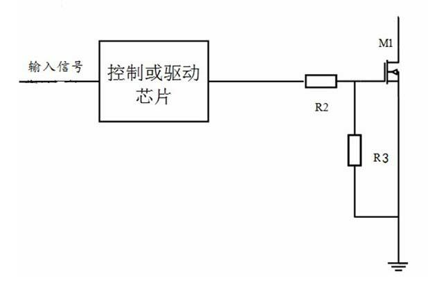
[0004] The technical problem of this direct drive circuit is: when the driven N-type MOSFET works in an aging or long-term radiation environment, its gate-level driving voltage will be significantly reduced, and in a high-irradiation environment, the gate-level conduction The voltage may even drop to a state close to zero voltage. At this time, it is difficult for the MOSFET to be turned off reliably, or to work in a linear region where it is not completely turned off.
The low level output by the drive or control chip is generally above zero level, and when the drive or control chip is aging or there is noise in the ground loop, the low level added to the gate level may make the MOSFET cannot be reliably fully shutdown, causing a malfunction

Method used


Image

  • Power switch tube drive circuit with negative pressure turn-off function
  • Power switch tube drive circuit with negative pressure turn-off function
  • Power switch tube drive circuit with negative pressure turn-off function

Examples


Embodiment Construction

[0016] In order to make the object, technical solution and advantages of the present invention clearer, the present invention will be further described in detail below in conjunction with the accompanying drawings and embodiments. It should be understood that the specific embodiments described here are only used to explain the present invention, not to limit the present invention.

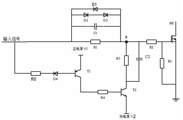
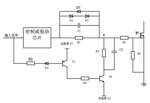
[0017] figure 2 The driving circuit of the power switch tube provided by the first embodiment of the present invention is shown. The primary side of the driving circuit is an input signal interface, through which the input signal from the control circuit enters the circuit of the present invention. The external input signal is connected to the input end of the driving or control chip, and the output end of the driving or control chip is connected to the voltage dividing resistor R1. The voltage dividing resistor R1 is connected to one end of the resistor R2, and the other end of the resistor R2 i...


PUM


Abstract

The invention, which is suitable for the electrical switch and switch power source fields, provides a power switch tube drive circuit with a negative pressure turn-off function. According to the embodiment of the invention, a negative pressure turn-off circuit is added on the basis of a traditional drive circuit; and an N type MOSFET can be reliably turned off on the condition that a gate level voltage is substantially reduced. Besides, diodes that are in obverse and inverse connection as well as in parallel connection are utilized, so that it is ensured that a driving chip has a normal switch speed on the MOSFET on the condition that there is a negative turn-off circuit.

Description

technical field [0001] The invention belongs to the field of electric switches and switching power supplies, in particular to a driving circuit of a power switching tube with negative pressure shutdown. Background technique [0002] For N-type MOSFETs, when they are aging or working in a radiation environment for a long time, their gate-level driving voltage will be reduced. In this way, the MOSFET cannot be turned off reliably, or the turned-off MOSFET is prone to false conduction. [0003] figure 1 The driving circuit of the low-side N-type MOSFET in the prior art is shown, and the circuit includes: a control or driving chip, resistors R2 and R3. The driving signal sent by the control or driving chip is directly added to the MOSFET gate level through the resistor R2. The resistance value of the resistor R2 is very small, which is used to suppress the oscillation generated by the equivalent inductance of the line. Resistor R3 is used to prevent false conduction of the MO...

Claims


Application Information

Patent Timeline
IPC IPC(8): H02M1/08
Inventor 付明王骞
Owner SHENZHEN ACAD OF AEROSPACE TECH
Learn More