Combined electrode column of vacuum arc extinguishing chamber

A vacuum interrupter, combined technology, used in high-voltage air circuit breakers, electrical components, electric switches, etc., can solve the problems of broken and scrapped epoxy resin and silica gel, weak heat dissipation capacity, and large investment, and achieves It is beneficial to convection and heat conduction heat dissipation, easy installation and replacement, and the effect of improving heat dissipation conditions

Active Publication Date: 2013-09-11
沈阳华利能源设备制造有限公司
View PDF4 Cites 0 Cited by
  • Summary
  • Abstract
  • Description
  • Claims
  • Application Information

AI Technical Summary

Problems solved by technology

[0002] In the prior art, the poles of the vacuum interrupter are usually solid-sealed poles, which are made by the APG (automatic pressure gel) process, which requires several sets of special automatic pressure gel molds, vacuum mixers, molding machines, post-processing For special equipment such as curing constant temperature heating box, the finished pole must be inspected by X-ray perspective to determine whether there are internal defects. Therefore, the investment in molds and equipment is large, and the production cycle is long, especially X-ray perspective inspection. A special high-power X-ray machine is required, which is very expensive, and a special lead room and labor protection measures are also required. Once a quality problem occurs during the sealing process, not only the epoxy resin and silicone parts of the pole need to be smashed and scrapped, Even the expensive vacuum interrupter may be scrapped at the same time, so the production is more difficult. With the increase of the voltage level, the size of the vacuum interrupter continues to increase, the difficulty of manufacture is also increasing, and the cost is increasing. In addition, because the vacuum interrupter is completely sealed inside the epoxy resin shell, the flow capacity is low, the heat dissipation capacity is weak, and the temperature rise of the pole is high. In severe cases, it may reach the glass transition temperature of epoxy resin , resulting in a major accident

Method used


Image

  • Combined electrode column of vacuum arc extinguishing chamber
  • Combined electrode column of vacuum arc extinguishing chamber
  • Combined electrode column of vacuum arc extinguishing chamber

Examples


Embodiment Construction

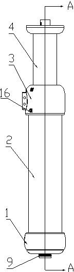
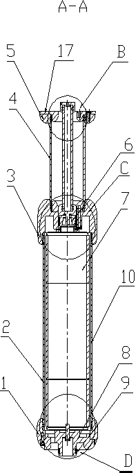
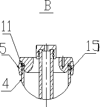
[0031] As shown in the drawings, the present invention includes a shielding electrode 1, a lower insulating cylinder 2, an upper outlet terminal 3, an upper insulating cylinder 4, an upper shielding ring 5 and a mounting flange 17, and the upper shielding ring 5 and the upper insulating cylinder 4 are connected to each other The first epoxy resin pouring point 11 composed of two annular grooves 15 is set at the position, and the second epoxy resin composed of two annular grooves 15 is arranged at the part where the upper insulating cylinder 4 and the upper outlet end 3 are connected to each other. The pouring point 12, the third epoxy resin pouring point 13 composed of two annular grooves 15 is set at the part where the upper outlet end 3 and the lower insulating cylinder 2 are connected to each other, and the third epoxy resin pouring point 13 is set at the part where the lower insulating cylinder 2 and the shielding electrode 1 are connected to each other There is a fourth ep...


PUM


Abstract

The invention relates to a combined electrode column of a vacuum arc extinguishing chamber which overcomes the problems of lower flow capacity and weaker heat radiating capability which may seriously reach the vitrification temperature of epoxy resin to cause major accidents in the traditional sealing electrode column. The combined electrode column is characterized in that epoxy resin perfusion points are arranged in the mutual connecting positions of an upper shielding ring, an upper insulating barrel, an upper wire outlet end, a lower insulating barrel and a shielding electrode; pre-mixed epoxy resin and a solidifying agent are perfused for firmly connecting the shielding electrode, the lower insulating barrel, the upper wire outlet end, the upper insulating barrel and the upper shielding ring together to form an outer cover of the electrode column; the vacuum arc extinguishing chamber is assembled in the outer cover of the electrode column; and the conductive connection of the electrode column is realized through a movable contact, a spring touching finger and a lower wire outlet end. The combined electrode column has the advantages that the manufacturing technology of the electrode column is simplified; the insulating capability of the electrode column is enhanced; the manufacturing cost of the electrode column is reduced; once the vacuum arc extinguishing chamber self has a quality problem, only the vacuum arc extinguishing chamber needs replacing; an outer electrode column still can be used continuously; and therefore, the installation and the replacement of the vacuum arc extinguishing chamber are convenient.

Description

technical field [0001] The invention belongs to the technical field of high-voltage electrical appliances, and in particular relates to a pole column of a combined vacuum interrupter used in a vacuum circuit breaker of a 126kV high-voltage system. Background technique [0002] In the prior art, the poles of the vacuum interrupter are usually solid-sealed poles, which are made by the APG (automatic pressure gel) process, which requires several sets of special automatic pressure gel molds, vacuum mixers, molding machines, post-processing For special equipment such as curing constant temperature heating box, the finished pole must be inspected by X-ray perspective to determine whether there are internal defects. Therefore, the investment in molds and equipment is large, and the production cycle is long, especially X-ray perspective inspection. A special high-power X-ray machine is required, which is very expensive, and a special lead room and labor protection measures are also ...

Claims


Application Information

Patent Timeline
Patent Type & Authority Patents(China)
IPC IPC(8): H01H33/66H01H33/664
Inventor 贾延超蔡强廖汉
Owner 沈阳华利能源设备制造有限公司
Why Eureka
Try Eureka