Radial-axial three-degree-of-freedom alternating current-direct current hybrid magnetic bearing

An AC/DC hybrid and magnetic bearing technology, which is applied in shafts, bearings, bearings, mechanical equipment, etc., can solve problems such as poor heat dissipation performance, reduced bearing capacity of magnetic bearings, limited space between axial control coils and radial control coils, etc. Achieve the effects of good heat dissipation performance, increased critical speed, and simplified drive control method

Active Publication Date: 2013-03-13
JIANGSU UNIV
View PDF6 Cites 9 Cited by
  • Summary
  • Abstract
  • Description
  • Claims
  • Application Information

AI Technical Summary

Problems solved by technology

[0005] The publication number is CN1737388, and the patent document titled "three-degree-of-freedom AC-DC radial-axial hybrid magnetic bearing and its control method" proposes that the magnetic bearing adopts a single-piece stator, and the stator is divided into an axial stator and a radial There are two parts to the stator, and the structure of the magnetic pole and the rotor is relatively simple. The disadvantage is that the space occupied by the axial control coil and the radial control coil is limited, resulting in a decrease in the bearing capacity of the magnetic bearing and poor heat dissipation performance.

Method used


Image

  • Radial-axial three-degree-of-freedom alternating current-direct current hybrid magnetic bearing
  • Radial-axial three-degree-of-freedom alternating current-direct current hybrid magnetic bearing
  • Radial-axial three-degree-of-freedom alternating current-direct current hybrid magnetic bearing

Examples


Embodiment Construction

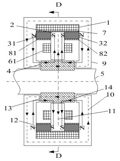
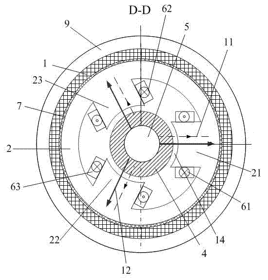
[0019] Such as figure 1 with figure 2 As shown, the present invention is an inner rotor magnetic bearing structure, which includes a rotating shaft 5, a rotor 4, a radial stator core 2 and an axial stator core 9 coaxially installed. The axial stator core 9 is the outer shell of the magnetic bearing and is located at the outermost periphery of the magnetic bearing. The cross section of the axial stator core 9 is a hollow cylindrical shape. The axial stator core 9 is sleeved on the shaft 5 and the axial stator core 9 is sleeved. In the radial stator core 2, an axial control coil 1 is provided in a cavity between the radial stator core 2 and the axial stator core 9. The radial stator core 2 is sleeved with a rotor 4, the rotor 4 is formed by laminating round silicon steel sheets, the cross section of the rotor 4 is a hollow cylindrical shape, and the rotor 4 is fixedly sleeved on the rotating shaft 5.

[0020] Both the rotor 4 and the radial stator core 2 are made of laminated sili...


PUM


Abstract

The invention discloses a radial-axial three-degree-of-freedom alternating current-direct current hybrid magnetic bearing used for non-contact suspension bearing. An axial control coil is arranged between a radial stator core and an axial stator core; an axial air gap is formed between the axial stator core and the end face of a rotor in the axial direction; three same stator core magnetic poles uniformly distributed in the circumferential direction extend from the wall of an inner cavity of the radial stator core to the axle center; same radial control coils are wound on the three stator core magnetic poles, and radial air gaps are formed between the stator core magnetic poles and the outer wall of the rotor in the radial direction; same axially magnetized annular permanent magnets are arranged between two axial sides of the radial stator core and the axial stator core; and S poles of the permanent magnets face the radial stator core, and N poles of the permanent magnets face the axial stator core. The radial-axial three-degree-of-freedom alternating current-direct current hybrid magnetic bearing integrates axial and radial functions, is only driven by a three-phase alternating current power inverter, is provided with two axially magnetized annular permanent magnets, controls the magnetic flux not to pass magnetic poles where the permanent magnets are positioned, and has the advantages of low power consumption, small volume, light weight and high bearing capacity.

Description

Technical field [0001] The invention relates to a non-mechanical contact magnetic bearing, in particular a radial-axial three-degree-of-freedom AC-DC hybrid magnetic bearing, which can be used as a five-degree-of-freedom magnetic suspension high-speed machine tool electric spindle, a bearingless motor, a flywheel energy storage system, and an air conditioner Non-contact suspension support for rotating parts in mechanical equipment such as compressors, turbomolecular pumps and spacecraft such as satellites and space stations. Background technique [0002] At present, hybrid magnetic bearings in which permanent magnets provide static bias magnetic flux and DC signals provide control magnetic flux have become a research hotspot at home and abroad, and focus on the study of axial single-degree-of-freedom magnetic bearings and radial two-degree-of-freedom magnetic bearings. There are few studies on radial-axial three-degree-of-freedom magnetic bearings. On the one hand, with DC contr...

Claims


Application Information

Patent Timeline
Patent Type & Authority Patents(China)
IPC IPC(8): F16C32/04
CPCF16C32/0465F16C32/0485
Inventor 张维煜朱熀秋
Owner JIANGSU UNIV
Why Eureka
Try Eureka