Swinging wing engine

An engine, wing type technology, applied in combustion engines, machines/engines, internal combustion piston engines, etc., to achieve the effects of simple and compact structure, short circulation paths, and low air leakage rates

Inactive Publication Date: 2012-01-04
SHENZHEN SAILANGKEN SCI & TECH
View PDF6 Cites 2 Cited by
  • Summary
  • Abstract
  • Description
  • Claims
  • Application Information

AI Technical Summary

Problems solved by technology

[0007] In order to solve the above-mentioned technical problems of the existing rotary engines, the present invention proposes a swing-wing engine with simple and compact structure, low noise, minimal friction loss, high efficiency, energy saving and environmental protection

Method used


Image

  • Swinging wing engine
  • Swinging wing engine
  • Swinging wing engine

Examples


Embodiment Construction

[0051] Below knot and accompanying drawing and embodiment the present invention will be further described:

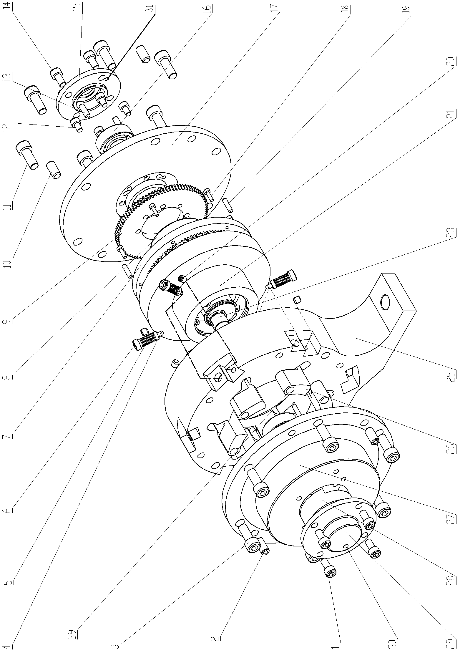
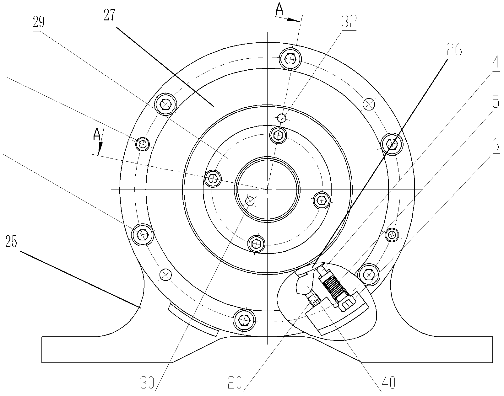
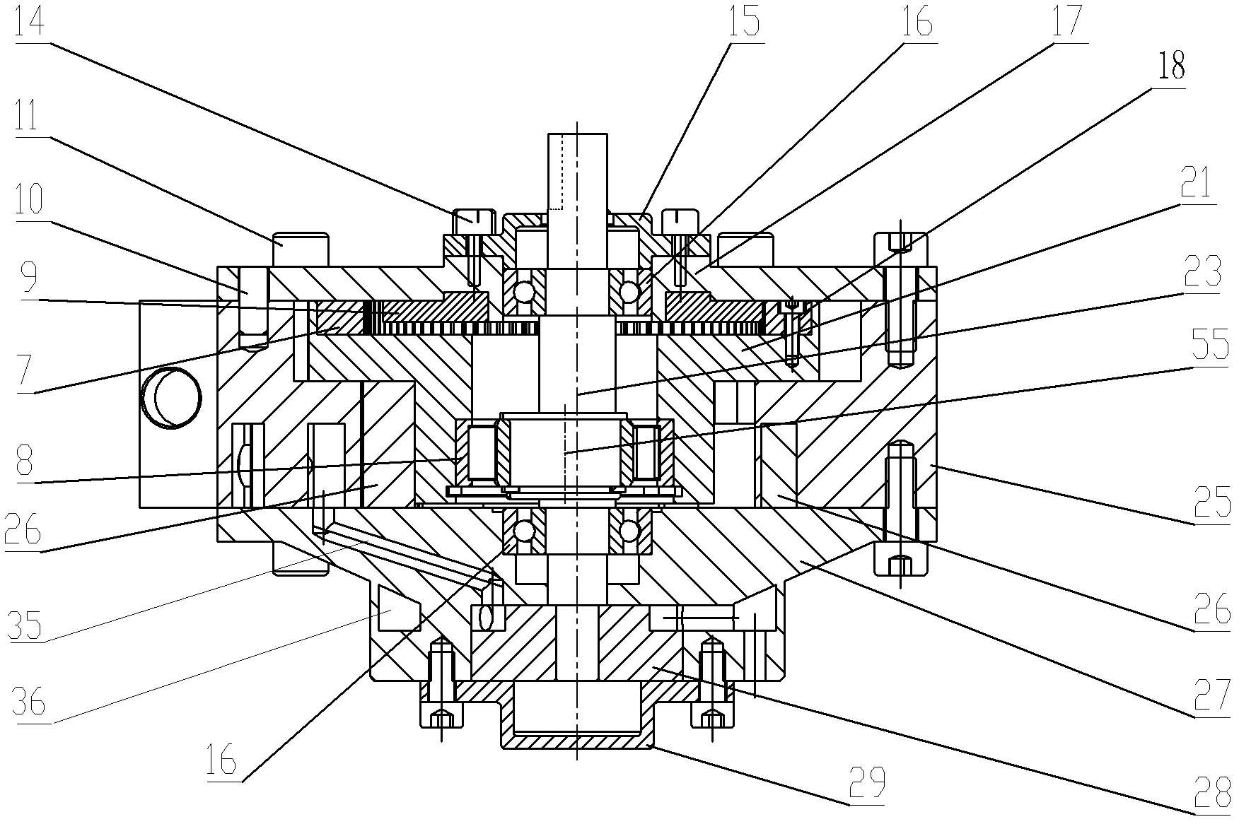
[0052] Such as Figure 1~4 As shown, the embodiment of the present invention provides a swing-wing engine, which includes a casing 25, a rotor 21 disposed in the casing, and an output shaft 23 installed coaxially with the casing. The middle part of this output shaft 23 is provided with an eccentric shaft section 55 (combined with Figure 9a ), and the inner circle 46 of the rotor 21 is connected with the eccentric shaft section 55 of the output shaft 23 through a rotor bearing 8, and the upward end surface of the rotor 21 is embedded with an internal meshing phase gear 7, and the two are connected by screws 18 and positioning pins 19 fixed (combined with Figure 8a , Figure 8b ). The upward facing end surface of the housing 25 is connected to the upper end cover 17 through positioning pins 10 and screws 11, while the inner surface of the upper end cover is connecte...


PUM


Abstract

The invention discloses a swinging wing engine. The swinging wing engine comprises a shell, a rotor and an output shaft which is coaxial with the shell. An eccentric shaft section is arranged in the middle of the output shaft; the inner circle of the rotor is connected with the eccentric shaft section through a rotator bearing; one end face of the rotor is embedded into an inner gearing phase gear; one end face of the shell is connected with an upper end cover and the inner surface of the upper end cover is provided with an outer gearing phase gear which is meshed with the inner gearing phasegear; the inner circle of the upper end cover is connected with the output shaft through a bearing; an upper bearing cover is connected with the upper end cover; other end face of the shell is connected with a distribution valve; the inner circle of the distribution valve is connected with the output shaft through the other bearing; a rotary valve which is connected with the output shaft is arranged in the inner circle of an outer end of the distribution valve; a lower bearing cover is connected with the distribution valve; a plurality of groups of swinging wing driving mechanisms which drivethe output shaft to rotate are arranged on an end face of the shell which is connected with the distribution valve along the inner circle of the shell; and the distribution valve and the rotary valveare also provided with air intake and exhaust passages which ensures the swinging wing driving mechanisms act; and the upper bearing cover is also provided with intracavity air overflow ports.

Description

technical field [0001] The present invention relates to an engine, in particular to an engine that utilizes the expansion or compression of a fluid (compressed air, hydrogen, natural gas, liquid, mixed gas formed by mixing fuel and air, etc.) A crankless rotary engine (motor) in which the rotor that rotates the follower moves eccentrically. Background technique [0002] Rotary engines mainly include engines in which the rotor rotates eccentrically, and generally have piston type and vane type. There are many piston types, especially the Wankel engine. Its structure generally consists of a special-shaped piston (rotor), an eccentric shaft, and a housing with a specific track. Its working principle is that the special-shaped piston (rotor) is eccentrically arranged relative to the shaft, and rolls along a specific track to change the volume to realize the process of suction, compression, work and exhaust. Compared with reciprocating engines, this type of engine is smaller i...

Claims


Application Information

Patent Timeline
Patent Type & Authority Applications(China)
IPC IPC(8): F02B53/02F02B53/04F02B55/10F02B55/02
CPCY02T10/17Y02T10/12
Inventor 谭善学
Owner SHENZHEN SAILANGKEN SCI & TECH
Why Eureka
Try Eureka