Display device and driving method of display device

A display device and display element technology, applied in the direction of identification device, static indicator, input/output process of data processing, etc., to achieve the effect of suppressing chromaticity difference and brightness difference

Inactive Publication Date: 2011-12-28
SHARP KK
View PDF7 Cites 12 Cited by
  • Summary
  • Abstract
  • Description
  • Claims
  • Application Information

AI Technical Summary

Problems solved by technology

However, since the increase in the size of the liquid crystal panel is accompanied by many technical constraints, an attempt has been made in the prior art to virtually realize the increase in size by combining a plurality of display devices.
[0003] However, based on this attempt, since each display device has a frame area, there is a problem that the joint between multiple display devices can be seen.

Method used


Image

  • Display device and driving method of display device
  • Display device and driving method of display device
  • Display device and driving method of display device

Examples


Embodiment approach 1

[0052] based on Figure 1 to Figure 9 One embodiment of the present invention is described below. However, unless otherwise specified, the dimensions, materials, shapes, and relative arrangements of components described in this embodiment are not intended to limit the scope of the invention thereto, but are simply descriptions. Just an example.

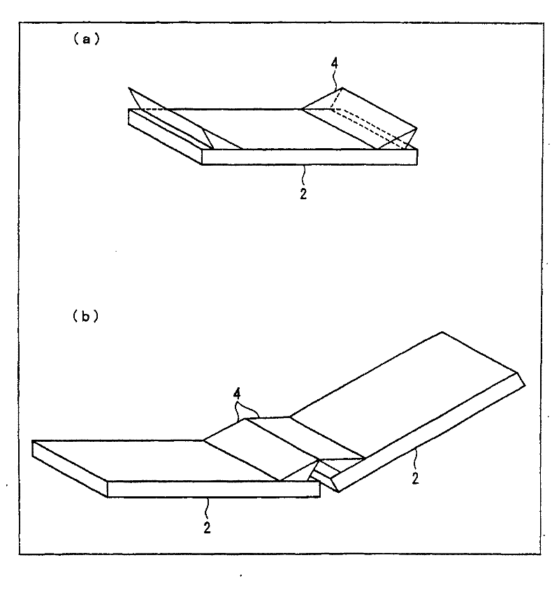
[0053] figure 2 It is a perspective view schematically showing the appearance of the display device of this embodiment. Hereinafter, in Embodiment 1, the display device will be described as a liquid crystal display device, but of course it is not limited thereto. figure 2 The liquid crystal display devices of (a) and (b) include a liquid crystal display panel 2 and a light guide element 4 . exist figure 2 In the liquid crystal display device of (a), two light guide elements 4 are mounted on the liquid crystal display panel 2 in the peripheral region along the two sides facing each other in the peripheral region of the rectangu...

Embodiment approach 2

[0123] according to Figures 10 to 13 Another embodiment of the present invention will be described below. In addition, for the sake of convenience of description, components having the same functions as those shown in the drawings of Embodiment 1 above are denoted by the same reference numerals, and description thereof will be omitted.

[0124] Figure 10 A plan view of the display device 1 is shown. The display device 1 includes: a display panel 2 , a light guide element 4 and a light sensor 100 . The optical sensor 100 may be installed at any position on the display device 1 as long as it is at a position where the ambient illuminance can be measured. Figure 10 An example in which one optical sensor 100 is provided on the outer frame of the display panel 2 is shown. In addition, the photosensor 100 may be provided adjacent to a pixel formation portion (display element) in the normal display area A1 of the display panel 2 or built into a certain pixel formation portion....


PUM


Abstract

Disclosed is a display device with a seamless display which allows display such that the viewer does not experience a feeling of discomfort or such feelings of discomfort are reduced. The display device is provided with: a display panel (2) wherein a plurality of display elements are arranged in matrix fashion and wherein a border region where the aforementioned display elements are not arranged is provided at the edge thereof; lightguide elements (4) provided on the aforementioned display panel (2) for guiding some of the light that is emitted from the aforementioned display elements onto the aforementioned border region by optical path conversion; an optical sensor (100) which is provided on the aforementioned display panel (2) and detects ambient illuminance; an image signal correction unit that outputs a corrected image signal by correcting an image signal that is supplied to the display elements of the region where the aforesaid lightguide elements (4) are provided in accordance with the detected ambient illuminance, so as to reduce the brightness of the display light of said image by means of the aforesaid lightguide elements (4), or so as to reduce the coloration thereof; and a drive unit that drives the aforesaid display elements in accordance with the aforesaid corrected image signal.

Description

technical field [0001] The present invention relates to a display device and a driving method of the display device, and more specifically, to a display device (hereinafter also referred to as a seamless display) for obtaining a single screen without a seam by using a plurality of display panels, and to driving the display device method. Background technique [0002] In recent years, as the demand for lightweight and thin displays has increased, active matrix liquid crystal display devices using particularly large liquid crystal panels have become more common. However, since the increase in the size of the liquid crystal panel is accompanied by many technical constraints, conventional attempts have been made to virtually achieve the increase in size by combining a plurality of display devices. [0003] However, based on this attempt, since each display device has a frame area, there is a problem that a joint between a plurality of display devices can be seen. This problem ...

Claims


Application Information

Patent Timeline
Patent Type & Authority Applications(China)
IPC IPC(8): G09G3/36G02F1/133G02F1/1333G09F9/40G09G3/20
CPCG09G2320/0285G09G2300/026G09G2310/0232G09G2360/144G09G2320/0673G09G3/30G09G2320/0242G02F1/133524G02F1/13336G06F3/1446G09G3/20G09G3/3611H04N13/0438H04N13/341
Inventor 今村健太郎吉田茂人
Owner SHARP KK
Why Eureka
Try Eureka