
An integrated treatment device and treatment process for exhaust gas containing dust and heat

A treatment device and treatment process technology, which is applied in the direction of combined devices, dispersed particle separation, chemical instruments and methods, etc., can solve the problems of waste of resources and heat energy, environmental pollution, etc., and achieve reduced heat energy consumption, improved heat exchange efficiency, and reduced water volume Effect

Active Publication Date: 2011-12-28
SINOPEC NANJING CHEM IND CO LTD +1
View PDF4 Cites 18 Cited by
  • Summary
  • Abstract
  • Description
  • Claims
  • Application Information

AI Technical Summary

Problems solved by technology

[0006] In order to solve the above-mentioned problems of environmental pollution in tail gas and waste of resources and heat energy, the present invention provides a device for integrated treatment of dust-laden and humid-heat tail gas material recovery and utilization of low-level heat energy

Method used


Image

  • An integrated treatment device and treatment process for exhaust gas containing dust and heat

Examples


Embodiment 1

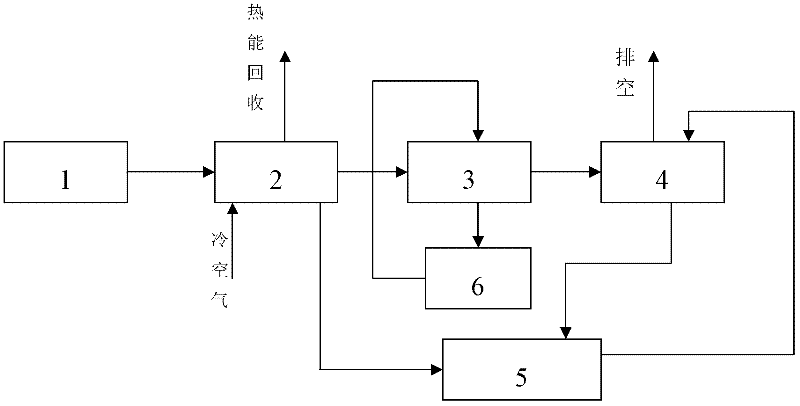
[0025] Such as figure 1 As shown, the dust-containing, humid-heat-containing exhaust gas integrated treatment device includes a dust removal device and a washing and absorption device, and the heat exchange equipment 2 is connected in series between the dust removal device 1 and the washing and absorption device 3 through pipelines. The liquid outlet of the heat exchange device 2 is connected to the circulating water tank 5 through a pipeline. The drain of the washing and absorbing device 3 is connected to the inlet of the circulating liquid tank 6 through a pipeline, and the outlet of the circulating liquid tank 6 is connected back to the second inlet of the washing and absorbing device 3 through a pipeline. That is, the circulating liquid tank 6 is connected with the washing and absorbing device 3 through pipelines to form a circulating loop. The exhaust port of the washing and absorbing device 3 is connected to the spray tower 4 through a pipeline. The spray tower 4 and t...

Embodiment 2

[0027] The process of using the dust-containing and humid-heat tail gas integrated treatment device of embodiment 1 for processing:

[0028] In the production process of sulfur-based compound fertilizer, the tail gas produced by the drying and granulation section: contains 2000ppm of ammonia and 16.3g / m of dust 3 And humidity (moisture content) 0.286kg water vapor / kg dry air, the temperature is 120~130℃, the exhaust gas flow rate is 1000m 3 / h.

[0029] a) Dust removal: the tail gas is passed into the diffusion cyclone dust collector 1 for dust removal, and the dust content of the tail gas after dust removal is 1.4g / m 3 , The dust removal efficiency is 92%, and the collected dust is returned to the production section as a material for reuse.

[0030] b) Heat exchange: The tail gas after dedusting is passed into the polytetrafluoroethylene shell and tube heat exchanger 2 for countercurrent heat exchange with the cold air to recover heat energy and reduce the temperature and h...


PUM

PropertyMeasurementUnit
dust removal efficiencyaaaaaaaaaa

Abstract

The invention discloses an integrated processor for a dirty, damp and hot tail gas and a technology thereof. The integrated processor which is arranged between a dust collector (1) and a washing and absorbing device (3) is connected with a heat exchange device (2) in series through pipelines. The technology comprises the following steps: the dirty, damp and heat tail gas is accessed to the dust collector (1) for separation and dedusting with the apparatus; the dedusted hot tail gas is accessed to the heat exchange device (2) for heat energy recovery; and the heat exchanged tail gas is successively accessed to the washing and absorbing device (3) and a spray tower (4) to absorb and reutilize a pollutive gas in the tail gas. The integrated processor has the advantages of simplicity and easy operation, and the discharge of the pollutive gas, a pollutive liquid and heat is reduced, the energy is saved, wastes are changed into valuables, and the enterprise cost is reduced by utilizing the integrated processor to process the tail gas.

Description

technical field [0001] The invention belongs to the technical field of tail gas energy saving and emission reduction, material purification treatment and recycling, and specifically relates to an integrated treatment device and process for tail gas containing dust and heat and humidity below 200°C. Background technique [0002] Pollutants such as dust and volatile components produced in the chemical production process are inevitably discharged into the atmosphere along with the dry tail gas, causing environmental pollution and waste of resources and heat energy. [0003] Taking the drying and granulation tail gas of sulfur-based compound fertilizer as an example, the dry and granulation tail gas of sulfur-based compound fertilizer contains a lot of ammonia, dust and water vapor, and its temperature is about 120-130 °C. Ammonia is a toxic gas with a pungent odor, especially irritating and corrosive to the upper respiratory tract of animals or humans; dust pollutes the atmosph...

Claims


Application Information

Patent Timeline
Patent Type & Authority Applications(China)
IPC IPC(8): B01D50/00B01D53/78B01D53/58
Inventor 黄和郝缠熙韩毓旺胡燚贾忱
Owner SINOPEC NANJING CHEM IND CO LTD
Learn More